Figure 2 – Mastercool 69300-220 TWIN TURBO REFRIGERANT RECOVERY SYSTEM User Manual
Page 4
4
www.mastercool.com
its capacity. When the Recovery System is started vapor from the recovery tank is compressed and sent,
at high pressure, to HVAC or refrigeration system. As pressure builds, the liquid is “pushed” out of unit into
recovery tank. Vapor from recovery tank is “pulled” out of recovery tank, compressed, and then pressurizes
unit.
Note: Some systems may not have liquid service port. This prevents the push-pull technique from being
used.
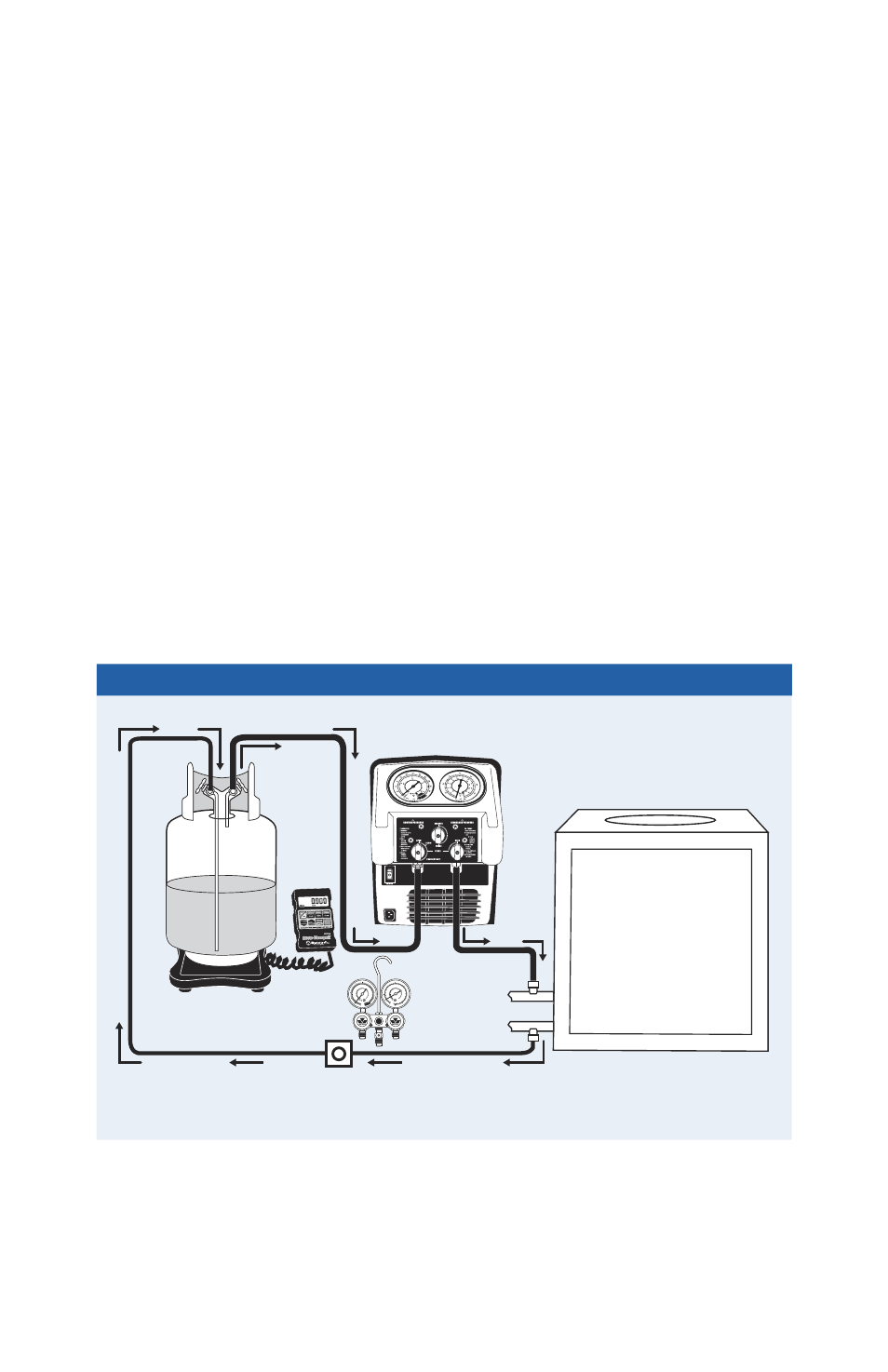
Procedure for Push-Pull technique (Connect system per fig. 2 and following instructions).
1. Connect outlet port of Recovery System to vapor port of unit to be serviced. Use hoses with automatic or
manual valves on both ends to prevent refrigerant release when disconnecting.
2. Connect liquid port on unit to be serviced to liquid port on recovery tank. Recovery tank should be on a
scale that stops flow when 80% tank capacity is reached. This connection should be made with a
manifold gauge set with sight glass to verify liquid flow. Recovery tank must have a minimum pressure
rating of 38 bar (550 psi).
3. Connect vapor port of recovery tank to inlet port of Recovery System. Use hose with automatic or manual
valve on both ends.
4. Open valves on unit to be evacuated. Open valves on recovery tank.
5. On Recovery System, rotate outlet valve to
“OPEN” position. Rotate center valve to “RECOVER” position.
Rotate inlet valve to
“OPEN” position.
6. Start Recovery System.
7. Check the sight glass for the presence of liquid flow. When liquid stops flowing, rotate inlet valve on
Recovery System to
“CLOSED” position. When Recovery system is shut down due to vacuum, turn OFF
the power switch. Reconnect system for direct vapor recovery following instructions listed under
“Operating Guide for Direct Vapor or Liquid Recovery”.
30
25
20
15
10
5
0
0
200
250
300
350
400
450
150
100
100
90
80
70
60
50
40
30
20
10
110
130
120
140
150
350
50
0
PSI
PSI
BAR
BAR
R134a
MC
R134a
MC
40
60
50
70
80
30
20
10
0
190
18
0
17
0
160
150
140
130
120
110
100
90
80
70
60
40
20
0
34
1
2
3
4
5
6
7
8
9
10
18
0
0
10
-10
-20
-30
20
30
40
10
20
-20
30
40
50
60
70
80
90
100
11
0
-40 F
RETA
RD
In Hg
VAC
10
20
30
Liquid
Vapor
�����
���
R
Air Conditioning
or
Refrigeration System
Recovery
System
���������������������
���������������������
Approved
Recovery
Tank
Use Sight Glass
or
Manifold W/Sight Glass
FIGURE 2