Mallory Ignition Mallory HYFIRE VIIC CONTROL UNIT 674M User Manual
Page 2
2
Additional Functions:
The HYFIRE
®
667C has two more functions that can make the ignition instal-
lation and setup work better. One of these is the high speed advance function.
This lets you put small amounts of timing in the engine after the torque peak to
pick up a bit of horsepower. There are three things that need to be set up for
this: the cut-in RPM (Mode 9), the maximum advance (Mode A), and the
slope (Mode 8). The cut-in RPM is the RPM where you want the curve to start
working. The slope is how much the timing will advance every 1000 RPM
after the cut-in RPM. The maximum advance is the highest amount of ad-
vance you want the system to reach.
For example, say that your engine has the torque peak at 6500 RPM, and
you want to add some timing after this. You might want to start adding timing
after 7000 RPM, so this becomes your cut-in speed. If you then want 2
degrees additional timing at 8000 RPM, then the slope would be set for 2
degrees per 1000 RPM. However, lets say that you dont want more than 2
degrees of advance, so you would set the maximum advance at 2 degrees.
See example 7 for more detail.
The other additional function available is trigger compensation, which is set
when the mode indicator is b. This lets you compensate for the various
delays in ignition timing caused by both electronic and mechanical changes.
To set the trigger compensation, set mode 9 to 5000 RPM, and mode 8 to
zero. What this does is tell the system to start the high-speed advance at 5000
RPM, but with a slope of zero, there should be no advance. Once the system
is set up this way, watch the timing as the engine revs past 5000 RPM. If the
timing does not stay at a steady value (once the 5000 RPM point is reached)
then adjust the compensation value until it is as flat as possible. For example,
if the timing retards slightly as the RPM goes up, increase the compensation
value. If the timing advances slightly as the RPM goes up, decrease the com-
pensation value.
NOTE: This function is only valid for RPM above the high-speed
advance cut-in RPM. If you have the high-speed advance cut-in set
above the normal operational range of the motor, the compensation
function does nothing.
Once the compensation is set, then the high speed advance settings will be
accurate. The factory setting should be correct for most types of flying magnet
type crank trigger systems, and should not normally need to be adjusted
unless you are using a different trigger type.
Number of cylinders selection
The final mode that can be set is mode C. This allows you to select 4 through
12 cylinder operation. This ensures that the RPML and the timing are proper
for the engine. Mode 6F is specialthis is for odd-fire V6 engines ONLY! The
cylinder firing spacing should be 45/75 (at the distributor) or 90/150 at the
crank.
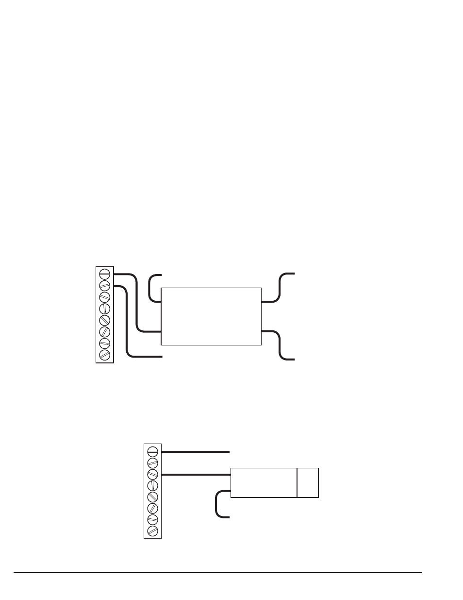
NC
N
NO
RPM2
RPM3
RET1
RET2
RET2
COIL
To +12 Volts
To Nitrous System
From Nitrous
Activation Switch
COIL
To Ground
CONTACT
CONTACT
RELAYUse a relay if you are
switching more than 3-5 amps.
EXAMPLE 1: Using the RPM switch (Mode 7) to turn OFF a nitrous system at a particular RPM.
(Not available when used with the HYFIRE
®
667S)
NC
N
NO
RPM2
RPM3
RET1
RET2
RET2
To Ground
To +12 Volts
EXAMPLE 1: Using the RPM switch (Mode 7) to turn ON a shift light.
(Not available when used with the HYFIRE
®
667S)