Maintenance – pump disassembly – Mallory Ignition Mallory COMP PUMP SERIES 250 ELECTRIC FUEL PUMP 5250_5250A User Manual
Page 4
4
www.mrgasket.com
MALLORY IS A DIVISION OF THE MR. GASKET PERFORMANCE GROUP
10601 MEMPHIS AVE. #12, CLEVELAND, OH 44144
216.688.8300FAX 216.688.8306
FORM 1038
(REV. F) 11/04
Made in U.S.A.
Printed in U.S.A.
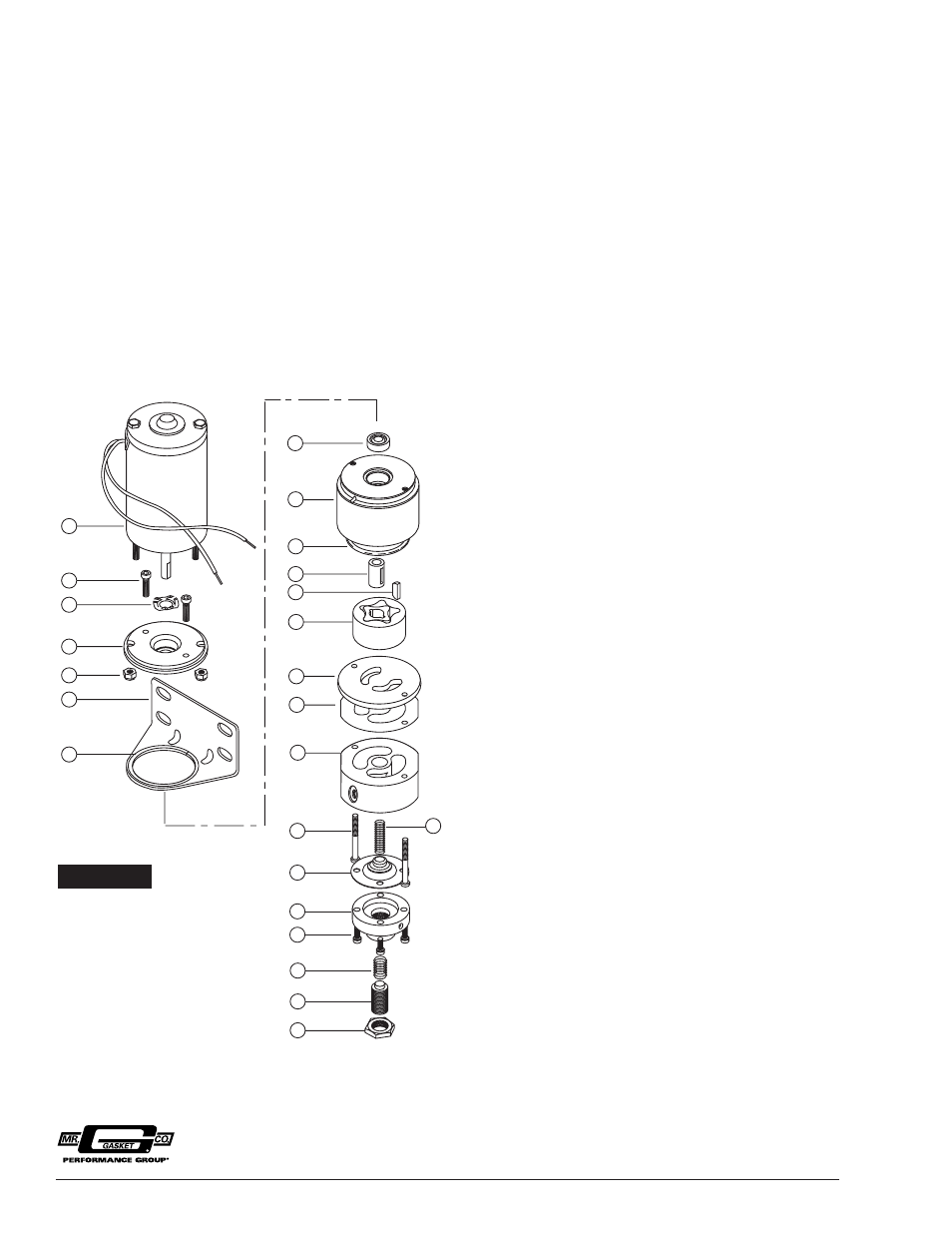
FIGURE 6
18
19
20
21
22
23
24
9
10
11
14
15
16
17
12
13
1
2
3
4
5
6
7
8
MAINTENANCE –
PUMP DISASSEMBLY
If your pump fails to produce adequate pressure or
volume, it may require cleaning. Follow the steps below to
disassemble and clean your Mallory Electric Fuel Pump.
Refer to Figure 6 while performing the following steps.
Step 1
Remove the pump from the vehicle and clean pump exterior.
Place the pump on its side on a clean work surface. Scribe
or draw a line across the pump housing, port plate and fuel
chamber so that you can reassemble the pump correctly.
Step 2
Remove the two fuel chamber screws from the bottom of the
pump. Remove fuel chamber and port plate from the pump.
NOTE: Do not drop the gerotor from the pump cavity.
Step 3
Place your hand beneath the gerotor and hold the pump in
an upright position. The gerotor should slide out of the
pump and into your hand.
Step 4
To disassemble the fuel chamber, first remove the lock nut
and adjusting screw, then turn the fuel chamber over so that
the diaphragm spring falls into your hand. Remove the four
screws holding the diaphragm cap to the fuel chamber.
Remove the diaphragm cap, diaphragm, and damper spring
from the fuel chamber.
Step 5
Clean the gerotor and reinstall it in the pump housing.
Inspect the O-ring and gasket, and replace them if
necessary. Inspect the diaphragm for any small tears or
bubbles in the surface, and replace it if necessary. Inspect
the gerotor housing and port plate for wear. If the generator
has worn through the plating, return the pump to Mallory
for repair.
Step 6
Assemble the pump in the reverse order that you
disassembled it. Test bypass pressure. Adjust bypass
so that pump is producing between 13 and 20 psi.
1. JAM NUT
2. ADJUSTING SCREW
*3. PRESSURE ADJUSTMENT SPRING
*4. CAP SCREW (4)
5. REGULATOR CAP
*6. GASOLINE DIAPHRAGM
ALCOHOL/METHANOL DIAPHRAGM
*7. FUEL CHAMBER SCREW
*8. DAMPER SPRING
9. FUEL CHAMBER
*10. FUEL CHAMBER GASKET
11. PORT PLATE
12. GEROTOR
*13. GEROTOR BUSHING KEY
*14. GEROTOR BUSHING
*15. O-RING
16. GEROTOR HOUSING
*17. SEAL
*18. BRACKET VIBRATION GASKET
19. BRACKET
20. MOTOR HOUSING NUT (2)
21. MOTOR ADAPTER
22. SPRING WASHER
23. MOTOR ADAPTER SCREW (2)
24. MOTOR
*THESE PARTS ARE INCLUDED IN SEAL / DIAPHRAGM KITS
PART NO. 3171 FOR GASOLINE
PART NO. 3172 FOR ALCOHOL
IMPORTANT: Turn fuel chamber screws by hand until they
contact the chamber. Then torque to 24 inch/pounds