Mounting procedure – Mallory Ignition Mallory COMP PUMP SERIES 110FI ELECTRIC FUEL PUMP 5110FI User Manual
Page 2
2
www.malloryracing.com
MALLORY IGNITION
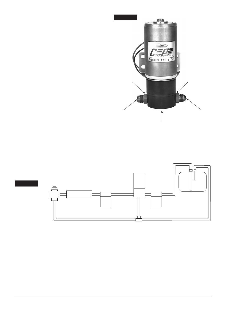
FUEL INJECTION
FUEL
FILTER
FUEL
FILTER
REGULATOR
FUEL
PUMP
FUEL RETURN
AIR BLEED
FUEL
TANK
COMP
Æ
�
FILTER
P/N 3160
COMP
Æ
�
FILTER
P/N 3140
or 3500
FIGURE 2
MOUNTING PROCEDURE
Step 1
Mount the pump as close as possible to the fuel tank
(at or below the level of the fuel tank pickup) in a well
ventilated area with minimal exposure to road debris.
Avoid exposing the pump and fuel lines to moving parts
and hot surfaces, such as the exhaust system. NOTE:
Increasing distance between the pump and tank will
decrease pump efficiency.
Step 2
Using the pump mounting bracket as a template, locate
mounting holes on a solid member, such as the vehicle
chassis. Drill clearance holes for 5/16” bolts. See
Figure 1.
Step 3
Connect 1/2” or larger fuel lines as shown in Figure 2.
The 1/8” NPT outlet on the bottom of the pump is for
an air bleed line to assist pump priming. This air bleed
line is not necessary if the regulated pressure of your
system is less than 10 psi. NOTE: Use a thread sealant
compound on the fitting threads. Don’t use thread
sealing tape because it could get into the Gerotor
and lock the pump.
Step 4
Your system must have a Return Style Fuel Pressure
Regulator near the injection system. See the General
Information section on page 1 for recommendations.
For maximum efficiency, mount the pressure regulator
as close as possible to the injection system. See instruc-
tions packaged with the regulator. The regulator may be
installed just before or just after the fuel injection.
FIGURE 1
AIRBLEED PORT
1/8” NPT
(BOTTOM)
NITRILE
O-RING
NITRILE
O-RING
FUEL INLET
3/4-16 x #8AN FLARE
FUEL OUTLET
3/4-16 x #8AN FLARE
RED WIRE (+)
(TOP)
BLACK WIRE (–)