General information, Hyfire, Ivc ignition system – Mallory Ignition Mallory HYFIRE IV SERIES Ignition System 692_697 User Manual
Page 2: Mounting procedure
2
GENERAL INFORMATION
The HYFIRE
®
IV Ignition System Part Nos. 692 and 697 are not for marine use.
The RPM limiter in the HYFIRE
®
IVC is not recommended as an engine speed governor. The
use of the RPM limiters is not recommended for applications equipped with a catalytic
converter. Similarly, forcing engine RPM past the RPM limiter continuously for long sustained
intervals can cause fuel build up in the exhaust system that may adversely affect your
application. The RPM limiting systems will not work properly with odd-fire V6 applications.
Ignition Ballast Resistor / Loom Resistance Wire
The performance of the HYFIRE
®
IV is not affected by the presence of the factory ignition
resistors or ignition ballast resistors in the wire from the ignition switch.
Standard Ignition Bypass (Bypass Connector)
The Bypass Connector (supplied) fits into the Ignition Control Harness to convert back to
standard ignition. If you use the Bypass Connector, use ignition ballast resistors designed for
your vehicles distributor and coil (see diagrams for more information). This bypass method
does not work with magnetic pickup distributor or crank trigger ignition. Racing Applications: It
is not necessary to install ignition ballast resistors. However, do not use the Bypass Connector
until the ignition ballast resistors are installed in the wire from the ignition switch.
Ignition Coils
The HYFIRE
®
IV Electronic Ignition Controls are designed to work with most original
equipment ignition coils. For optimum performance use the Mallory PROMASTER
®
Coil Part
No. 29440 (up to 7,500 RPM) or Part No. 29625 (up to 10,000 RPM).
Fuel Injection
Some fuel injection systems need a voltage spike signal from the ignition coil before it will
operate properly. This signal changes once HYFIRE
®
IV Electronic Ignition Controls are
installed. The Mallory Fuel Injection and Tachometer Adapters Part Nos. 29074 and 29078
supply the proper signal to the vehicle computer to operate the fuel injection system.
Installation procedure and diagrams are supplied with these adapters.
Spark Plug Wires
YOU MUST USE suppression type (carbon core, spiral core, suppression core) spark plug
wire. We recommend spiral core ignition wire, such as Mallory PRO SIDEWINDER
®
Ignition
Wire. Suppression type spark plug wires prevent false triggering and possible premature
ignition or accessory failures. DO NOT USE solid core (copper core; stainless steel core)
spark plug wire with any electronic ignition system or accessory.
Spark Plug Gaps
For street applications, use your engine manufacturer's specifications. For racing applications,
start with your engine manufacturer's specifications, then experiment with, and closely monitor,
various gaps to achieve maximum performance.
Electric Welding
Unplug the Ignition Control Harness from the HYFIRE
®
IV Electronic Ignition Control and
unplug any distributor harnesses (if possible) before any welding is done on the vehicle.
External RPM Limiters
Mallory Proportional RPM Limiter Part Nos. 641-4, 641-6, 641-8, 642, 643 and 644 WILL NOT
function with the HYFIRE
®
IV Electronic Ignition Controls.
Mallory PRO TACH
®
I, IV and VI
The RPM needle and shift light will work with the HYFIRE
®
IV. However, the tach's proportional
controller that limits RPM WILL NOT function with the HYFIRE
®
IV. Turn the LIMIT RPM knob
slightly past 11,000 to prevent the limiter from interfering with the tachs other functions. See
Optional Ignition Accessories for more information.
HYFIRE
®
IVC IGNITION SYSTEM
4 AND 6 CYLINDER OPERATION
The HYFIRE
®
IVC Ignition System comes from the factory set for 8 cylinder engines. 4 or 6
cylinder operations require you to set a switch inside the housing. DO THIS BEFORE
MOUNTING THE IGNITION BOX!
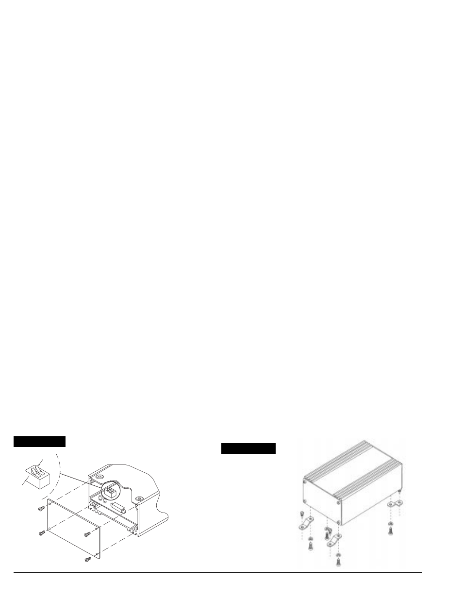
Use a T-15 Torx
®
tool to remove the four screws that holds the blank end panel to the
housing. Remove the blank end panel (see Figure 1).
With the ignition upside-down, look inside and on the left side of the PC board you will
see a small two position switch. The switch (#1) nearest the end of the PC board is the 6
cylinder switch. The other switch (#2) is the 4 cylinder switch. These switches are OFF
for 8 cylinder engines. Turn the appropriate switch ON for 4 or 6 cylinder operations.
Attach the blank end panel to the housing.
MOUNTING PROCEDURE
Step 1
Disconnect the battery () cable to cut power to the system. Computerized vehicles:
Disconnect the battery () cable and let the vehicle sit overnight before proceeding. This allows
the computer to calibrate for the new ignition.
Step 2
Select a convenient location to mount the HYFIRE
®
IV Electronic Ignition Control. Keep the
unit away from hot engine components or extreme heat such as the exhaust system and
manifolds. Also, keep it away from moving devices, such as fans, belts and linkages. The
location must be dry. Moisture will damage components inside the unit.
Step 3
Choose one mounting method listed below for mounting the HYFIRE
®
IV Electronic Ignition
Control (3a, 3b, or 3c).
(3a) Mounting to a flat surface without brackets
Center punch the mounting pattern on the mounting surface using the mounting
template to mark locations for drilling mounting holes. Drill holes using a 7/32" drill bit.
Hold the HYFIRE
®
IV Electronic Ignition Control in position over the mounting holes.
From the backside of the mounting surface, insert the 10-32 screws with lock washers
through the mounting holes and into the tapped holes in the bottom plate of HYFIRE
®
IV
Electronic Ignition Control. Tighten each screw until snug.
(3b) Mounting to a flat or uneven surface using brackets
Refer to Figure 2 while performing the following steps.
Position one hole of each bracket over each tapped hole in the bottom plate of the
HYFIRE
®
IV. Insert 10-32 screws with lock washers through these holes and into the
tapped hole in the bottom plate of the HYFIRE
®
IV. Tighten each screw until snug.
Hold the HYFIRE
®
IV in position where it will be mounted. Bend the brackets slightly to
meet uneven surfaces. Center punch the mounting pattern on the mounting surface to
mark locations for drilling mounting holes. Drill holes using a 9/64" drill bit.
Insert the #10 sheet metal screws through the remaining holes in the mounting brackets
and into the holes in the mounting surface. Tighten each screw until snug.
(3c) Mounting to a flat surface with shock mounts (available separately)
Center punch the mounting pattern on the mounting surface using the mounting
template to mark locations for drilling mounting holes. Drill holes using a 7/32" drill bit.
Install the shock mounts into the bottom plate of the HYFIRE
®
IV. Hold the unit in position
where it will be mounted.
From the backside of the mounting surface, insert the 10-32 nuts with lock washers onto
the shock mount studs. Tighten each nut until snug.
FIGURE 2
4 CYL
4 - 6 CYL
SWITCH
6 CYL
BOTTOM
OF
1
2
FIGURE 1