Mallory Ignition Mallory NITROUS 6 ELECTRONIC IGNITION CONTROL 6865M User Manual
Page 6
6
www.malloryracing.com
MALLORY IGNITION
Ford: Install the diode inline to the wire
going to the #1 terminal.
GM:
Install the diode inline to the wire
going to the #4 terminal.
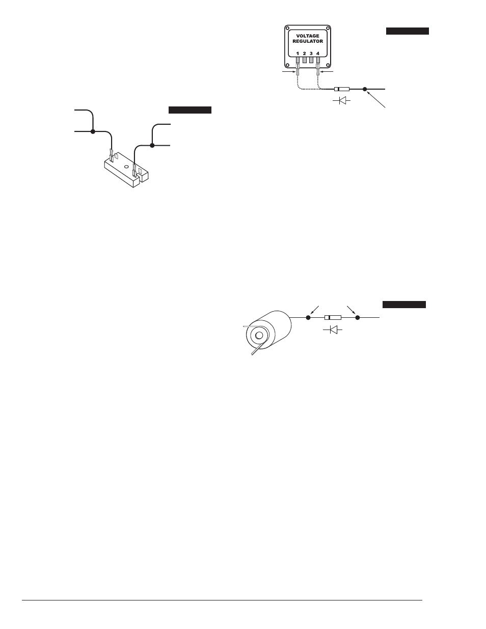
GM 1973-83 with Delcotron Alternators
GM Delcotron alternators use an internal
voltage regulator. Install the diode inline on
the smallest wire exiting the alternator (see
Figure 5). It is usually a brown wire.
Most other applications: To eliminate run-on,
place a resistor in-line to the NITROUS 6
small red wire to keep voltage from leaking
into the NITROUS 6 Ignition.
Misses and Intermittent Problems
Experience has shown that if your engine is
misfiring or hesitating at higher RPM, it is
usually not an ignition problem. Most
common causes include a coil or plug wire
failure, arcing from the cap or boot plug to
ground or spark ionization inside the cap.
Perform the following checks:
• Inspect the plug wires at the cap and at
the spark plug for a tight connection.
Visually inspect for cuts, abrasions, or
burns.
Ballast Resistor
If you have a current trigger tach (originally
connected to coil (+) positive) and use the
green wire of the NITROUS 6 for triggering,
you can purchase a Chrysler Dual Ballast
Resistor (1973-76 applications).
Engine Run-On
If your engine continues to run even when
the ignition is turned off, you are experiencing
engine run-on. Usually, older vehicles with
an external voltage regulator are susceptible
to this condition. Because the NITROUS 6
Ignition Control receives power directly from
the battery, it does not require much current
to keep the unit energized. If you are
experiencing run-on, it is due to a small
amount of voltage going through the
charging lamp indicator and feeding the
small red wire (even if the key is turned off).
Early Ford and GM: To solve the run-on
problem, a diode is supplied with the
NITROUS 6 Ignition Control. By installing
this diode in-line of the wire that goes to the
charging indicator, the voltage is blocked from
entering the NITROUS 6 Ignition Control.
Figure 4 shows the proper diode
installation for early Ford and GM vehicles.
NOTE: Diodes are used to allow voltage
to flow only one way. Make sure the diode
is installed facing the proper direction, as
shown in Figure 4.
SMALL RED
FROM HYFIRE
®
VIA
12 VOLT
IGNITION SWITCH
CHRYSLER DUAL
BALLAST RESISTOR
WHITE WIRE FROM
HYFIRE
®
VIA
FROM POINTS OR
AMPLIFIER
FIGURE 3
FOR EARLY GM VEHICLES
ATTACH DIODE TO
#4 TERMINAL
FOR FORD VEHICLES
ATTACH DIODE TO
#1 TERMINAL
1A-100V DIODE
TO CHARGING LIGHT
SPLICE HERE
FIGURE 4
DELCOTRON
ALTERNATOR
1A-100V DIODE
TO CHARGING LIGHT
SPLICE HERE
FIGURE 5