Accel/dfi, Figure a, Figure b – Mallory Ignition ACCEL CHEVROLET APPLICATIONS (including LT-1) 74022 User Manual
Page 13
22
ACCEL/DFI
ACCEL/DFI
23
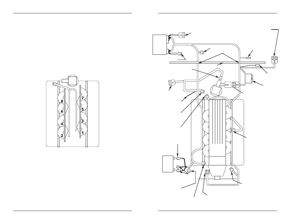
Figure A
3 PIN Green Connector
to MAP Sensor
5 PIN White
Connector to Main
Harness (Female)
+12V Switched
to Fuse Box
1 PIN Black
Connector to ESC
4 PIN Black Connector to
Computer Controlled HEI
2 PIN Grey Connector
to Air Temp. Sensor
2 PIN Black Connector to
Water Temp. Sensor
3 PIN Black Connector
to TPS Sensor
4 PIN Black Connector
to IAC Motor
Black/White Black
Black/Purple to Battery
Ground (-)
Red to Battery
Positive (+)
5 PIN Black
Connector to Injector
Harness (Male)
Grommet
Firewall
1 PIN Brown Connector
to Tachometer Pickup
for Non-Computer
Controlled HEI
3 PIN Black
Connector to
O2 Sensor
Red/White to Fuel
Pump Positive (+)
Figure B
Bypass Wire
6 Pin Power
Tuner Connector
4 Pin Calmap
Connector
30 AMP Fuse
3 AMP Fuse
See also other documents in the category Mallory Ignition For the car:
- Mallory ELECTRIC FUEL PUMP TROUBLESHOOTING GUIDE (2 pages)
- Mallory MAX-FIRE AND E-FIRE ELECTRONIC DISTRIBUTORS 2248214_2248204_2255104_2255404_2256704 (8 pages)
- Mallory COMP 9000 90 SERIES POINT TYPE DISTRIBUTOR (3 pages)
- Mr_Gasket ELECTRIC (MICRO) DIESEL FUEL PUMP 12D (4 pages)
- Mallory ENGINE MODIFICATIONS FOR O-RING DISTRIBUTORS (1 page)
- ACCEL AFTERBURNER SWITCHABLE COIL 140025 (4 pages)
- ACCEL DUAL TOWER COILS 140403/140403S/140404/140404S (2 pages)
- ACCEL COIL KIT 140405 (2 pages)
- ACCEL COIL KIT 140408, 140408BK, 140408CH (1 page)
- Lakewood safety bellhousing 15060 (5 pages)
- Lakewood Safety Bellhousing 15100/15120 (4 pages)
- ACCEL Battery Eliminator 151308 (1 page)
- Lakewood Safety bellhousing 15210_15220 (2 pages)
- Lakewood safety bellhousing starter 15320_15330 (2 pages)
- LAKEWOOD DRIVE SHAFT SAFETY LOOP 18005 (2 pages)
- LAKEWOOD FRONT DRIVE SHAFT SAFETY LOOP 18023 (1 page)
- LAKEWOOD REAR DRIVE SHAFT SAFETY LOOP 18024 (1 page)
- LAKEWOOD REAR ANTI-ROLL BAR CENTER LINKS 19101 (1 page)
- ACCEL Exhaust Wrap 2002bk_2002ta (2 pages)
- ACCEL POINTS ELIMINATOR IGNITION MODULE PN 2005 (2 pages)
- ACCEL POINTS ELIMINATOR CONVERSION 2010 (3 pages)
- Lakewood subframe connector 30201_20102 (1 page)
- LAKEWOOD REAR LOWER CONTROL ARMS 20105 (2 pages)
- ACCEL VOLTAGE REGULATOR 201104 (1 page)
- ACCEL VOLTAGE REGULATOR 201107_201107C (1 page)
- Lakewood TOE LINKS 20141_20142 (1 page)
- Lakewood REAR TRAILING ARM 20143 (1 page)
- Lakewood REAR UPPER CONTROL ARMS 20144_20149_20154 (2 pages)
- Lakewood REAR UPPER CONTROL ARMS 20152 (2 pages)
- Lakewood COIL SPRING TRACTION BAR 20188 (2 pages)
- Lakewood TRACTION BARS 20189 (2 pages)
- ACCEL POINTS ELIMINATOR CONVERSION 2020 (3 pages)
- ACCEL POINTS ELIMINATOR CONVERSION 2030 (3 pages)
- Lakewood Bolt-on Ladder Bars 20460 (1 page)
- Lakewood Competition Bolt-on Ladder Bars 20462 (1 page)
- Lakewood watts link 20505 (2 pages)
- Lakewood REPLACEMENT HARDWARE KIT FOR 20536 LADDER BARS (1 page)
- Lakewood REAR UPPER CONTROL ARMS 21101_21102_21103 (2 pages)
- Lakewood SUSPENSION BARS 21150 (2 pages)
- Lakewood Qwik Links 21200_21201_21202 (1 page)
- Lakewood LIFT BARS 21312_21313 (4 pages)
- Lakewood LIFT BARS 21314 (4 pages)
- Lakewood LIFT BARS 21700 (4 pages)
- Lakewood traction bars 21715 (2 pages)
- Lakewood traction bars 21720 (2 pages)