Lightronics RA122 User Manual
Page 8
Page
8
of
20
RA – 122 RACK MOUNT ARCHITECTURAL DIMMER
Revision 0.93
OWNERS MANUAL
09/26/2011
www.lightronics.com
Lightronics Inc.
509 Central Drive Virginia Beach, VA 23454
Tel 757 486 3588
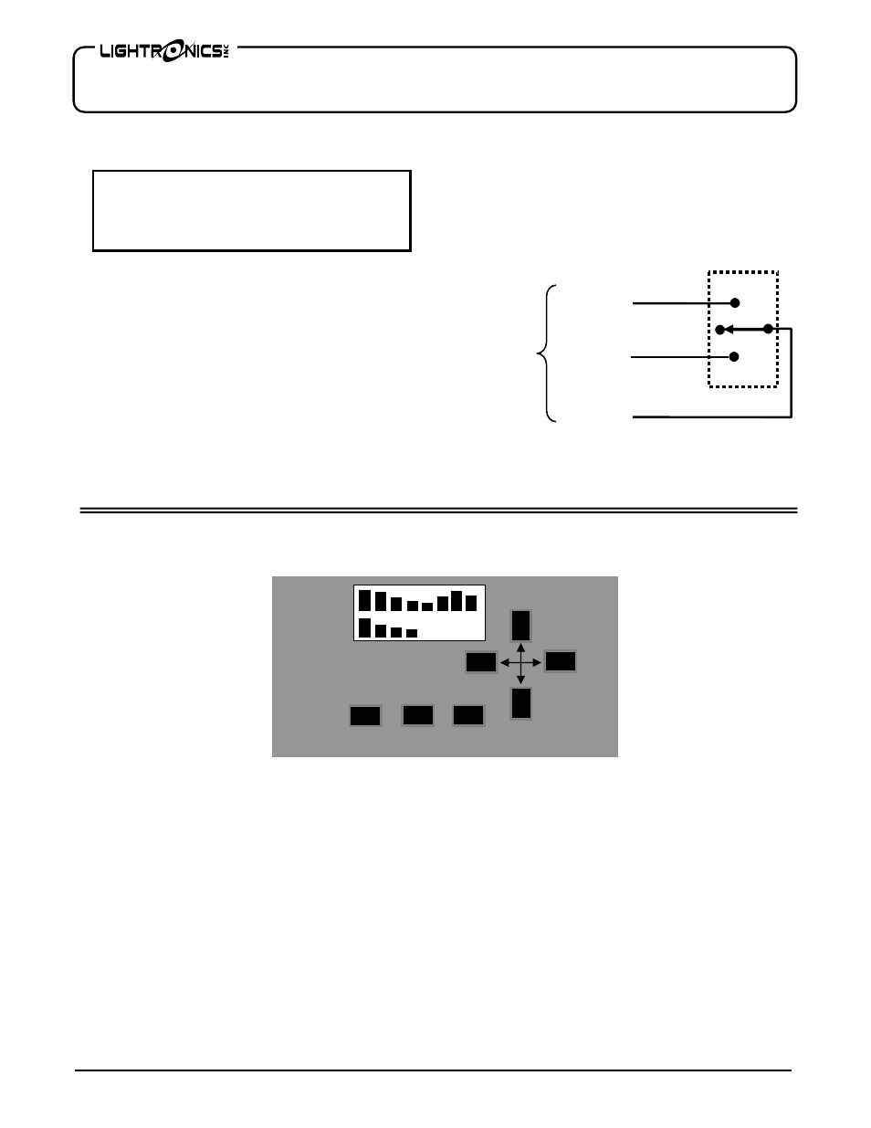
SIMPLE REMOTES CONNECTIONS
Scenes 1 - 7 (stored in the RA-122) may be accessed by
simple remotes. A BLACKOUT FUNCTION may also
be accessed. A simple remote is any switch which can
provide a momentary contact closure that can be applied
to a specific pin on the RA-122 CONTROL SIGNALS
CONNECTOR (DB25 connector).
The SIMPLE REMOTE COMMON is routed to the
remote. When the remote is operated the closure brings
the signal back to the applicable simple scene number
connection point at the RA-122 CONTROL SIGNALS
CONNECTOR (DB25 connector).
Since these are contact closures almost any available
low voltage wire may be used.
An example of a simple remote connection using a
Lightronics APP01 is shown below.
RA-122 UNIT SETUP
The RA-122 must be set up (configured) as part of the
installation process in any application. This set up
process is done from the front panel of the unit using
five menus which are described below.
SYSTEM SETUP should be done first. It includes:
setting the System Mode, System ID, and System
Power Setup.
DIMMER SETUP should be done next. It includes
Channel Limiting and Dim/Non-Dim selection.
DMX I/O SETUP must be performed if the unit will
be used with a DMX console. This setup assigns
(patches) dimmer channels to DMX channels and can
lockout the wall remote stations.
SCENE SETUP must be performed to create scene
presets to be activated from the remote control
stations or by the clock/timer subsystem.
EVENT SETUP must be done if the clock/timer
subsystem will be used. It includes Setting the Clock
and Programming Events.
FRONT PANEL (PARTIAL VIEW)
D
CONFIG CLEAR ENTER
SIMPLE REM
COMMON
TO
RA-122
DB25
CONNECTOR
SIMPLE REM
SCENE X
SIMPLE REM
SCENE 8
(BLACKOUT)
CAUTION
REMOVE ALL POWER FROM THE RA-122
BEFORE MAKING OR CHANGING SIMPLE
REMOTE CONNECTIONS.