Ra – 122 rack mount architectural dimmer – Lightronics RA122 User Manual
Page 6
Page
6
of
20
RA – 122 RACK MOUNT ARCHITECTURAL DIMMER
Revision 0.93
OWNERS MANUAL
09/26/2011
www.lightronics.com
Lightronics Inc.
509 Central Drive Virginia Beach, VA 23454
Tel 757 486 3588
LOAD CONNECTIONS
The RA-122 is supplied with one of several different
rear load connection panels. In all cases the lowest
number dimmer channel output connection is on the
left when the unit is viewed from the rear panel.
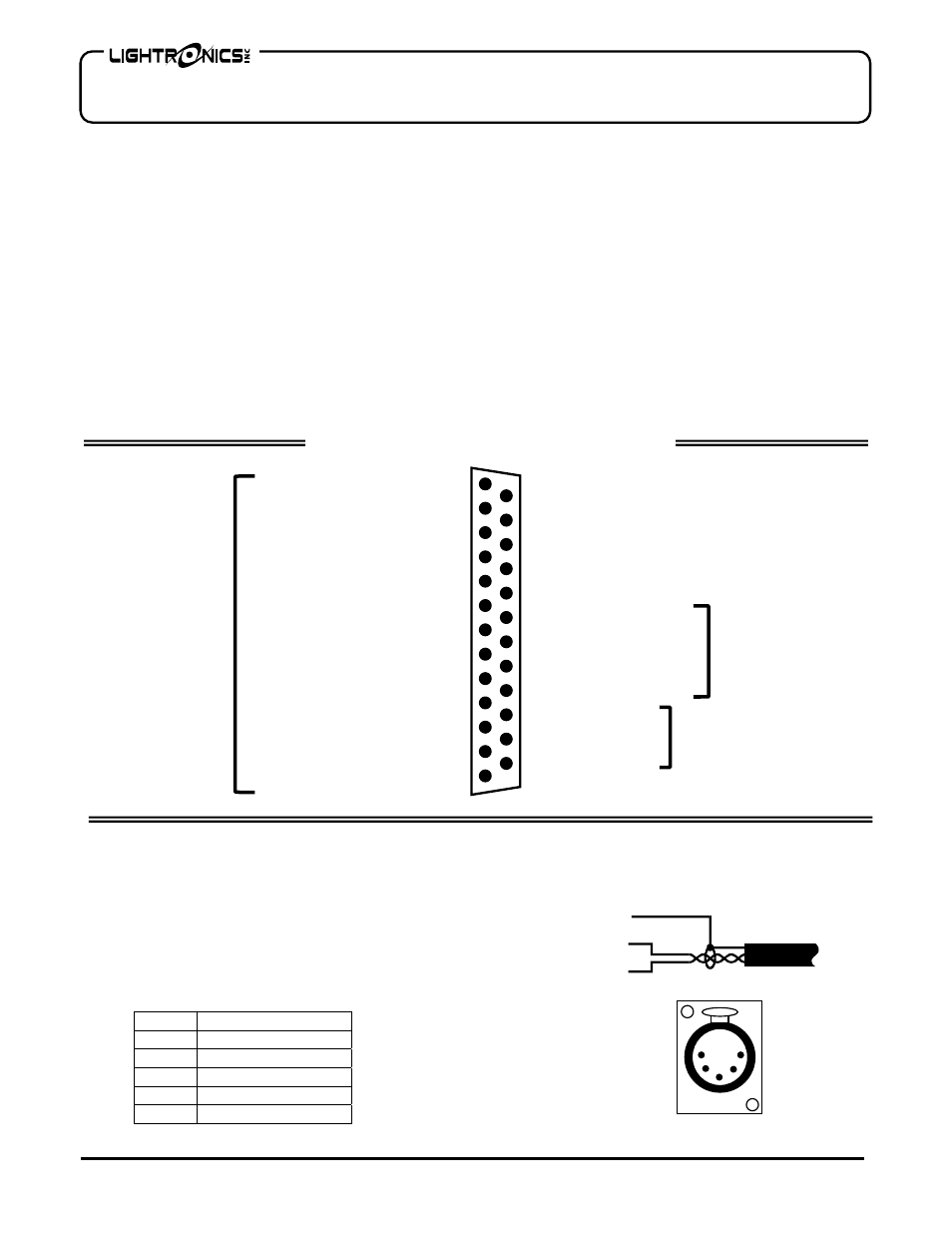
CONTROL SIGNALS CONNECTIONS
Two male DB25 connectors are provided at the rear of
the RA-122 to accommodate all external control
signals. Specific pins on the DB25 connector are used
to connect each different type of control device.
Control devices include a DMX console, multi-scene
remotes, and simple remote stations.
One of the connectors is used for control signal input,
the other is to pass the control signals to another RA-
122. The connectors are "hardwired" together so either
one can be used for "in" or "out".
The RA-122 is supplied with a ribbon cable which can
be used to chain multiple RA-122 dimmers together in
a rack.
A cable mount, female, DB25 connector is also
provided to accommodate all external control signals.
Wiring pin-out for the DB25 connectors is shown
below.
DMX CONSOLE CONNECTIONS
DMX console signals to the RA-122 should be
transmitted over a twisted pair, shielded, low
capacitance cable. Wiring data for DMX cabling is
shown below. A DMX console transmits from a
female, 5 Pin XLR Connector.
1
2
3
5
4
13
12
11
10
6
7
8
9
14
15
16
18
17
25
24
23
19
20
21
22
Simple Rem Scene 1
Simple Rem Scene 3
Simple Rem Scene 2
Simple Rem Scene 4
Simple Rem Scene 5
Simple Rem Scene 6
Simple Rem Scene 7
Simple Rem Scene 8 (Blackout)
Simple Rem Common
N/C
N/C
N/C
N/C
N/C
N/C
N/C
N/C
N/C
Smart Rem Common
Smart Rem Data -
Smart Rem Data+
Smart Rem V +
DMX Common
DMX Data -
DMX Data+
DMX BUS
SMART
REMOTE
BUS
SIMPLE
REMOTE
BUS
CONTROL SIGNALS CONNECTOR (DB25)
PIN # FUNCTION
1 DMX
COMMON
2
DMX DATA -
3
DMX DATA +
4 NOT
USED
5 NOT
USED
Common
DMX Data -
DMX Data +
Shield
DMX CABLE
CONDUCTOR ARRANGEMENT FOR
TWISTED PAIR, SHIELDED CABLE
1
2 4
3
5
5 PIN FEMALE
XLR CONNECTOR
DMX XLR CONNECTOR SIGNALS