Tb1-4, Tb1-3, Signal out – Liquid Controls IT150N User Manual
Page 10: Function selection, Miscellaneous
Sponsler, Inc.
IT150N Remote Totalizer
pg
10
DOC# MN-150N-B
FUNCTION SELECTION
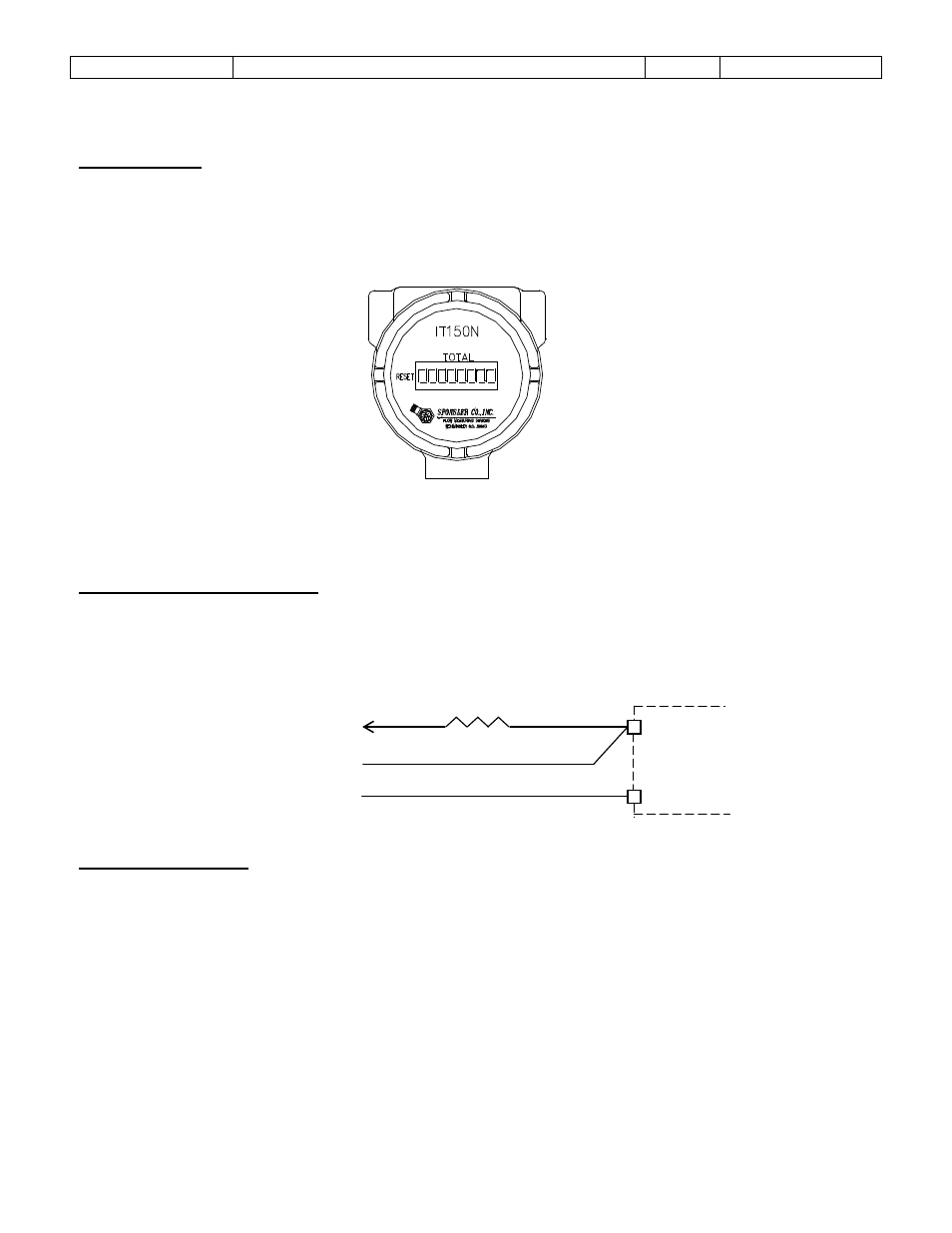
Reset Function
Reset is incorporated to set the Display to 00000000.
Reset is initiated externally by placing a magnet in the proximity of reset S7 located on the Display
P.C.B. and indicated on the enclosure label as ‘RESET’.
FIGURE 4
MISCELLANEOUS
Factored Digital Pulse Output
This signal is an open drain configuration which can sink 1A continuously. The maximum drain voltage
should not exceed 150VDC (V+). A pull-up resistor must be in series with V+ and TB1-3. The output is
a 2ms negative pulse for each increment of the totalizer; i.e. 1 pulse for each count on the LCD.
Typical Configuration-
Battery Replacement
The battery is located on the Mounting P.C.B. and inserts into 2 sockets. When installing the battery, it is
imperative to OBSERVE POLARITY. Simply pull the 3-board stack (See Figure #5) out of the enclosure,
install the battery and reinsert the board stack. The display will be all zeros.
IT150M
SIGNAL OUT +
SIGNAL OUT –
(V-)
V+
TB1-3
TB1-4
RL