Warning, Maintenance – Liquid Controls Mechanical Eliminators User Manual
Page 18
18
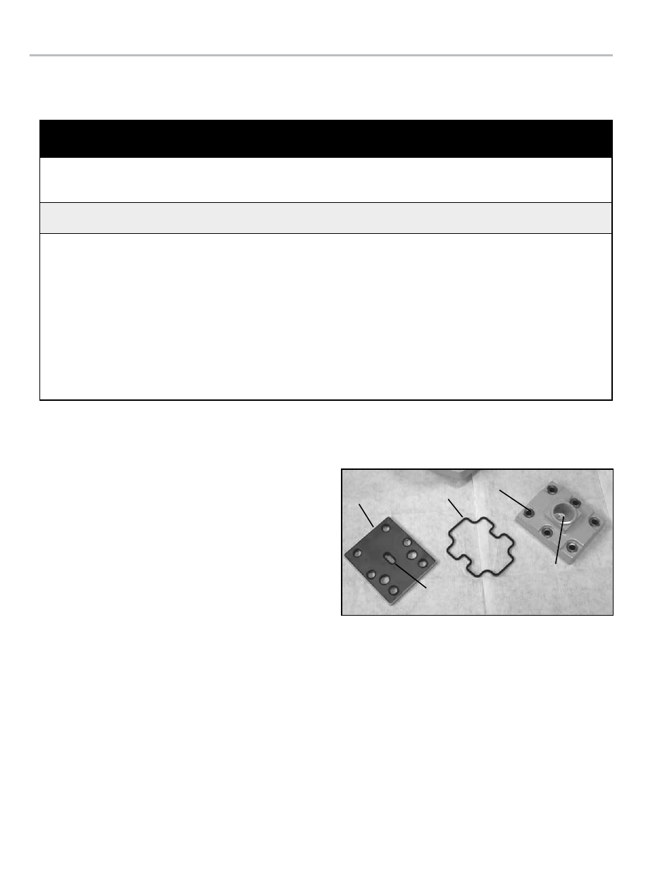
To replace the valve Plates & Cover Gaskets
1. Remove the cover screws from the air eliminator cover
with a 1/2 inch wrench or socket, and pull the cover, vent
plate and seal ring from the housing.
2. Inspect the raised ridge of the vent port opening in the
middle of the valve plate for marring or debris. Inspect the
seal ring for damage.
3. Replace the seal ring and/or valve plate. Tighten the
cover screws to a torque of 17.5 - 20.5 ft-lbs.
Maintenance
The most common indication of mechanical air and
vapor eliminator failure is leakage in and around the
cover and valve plate area. Common causes of air
eliminator failure are valve plate wear, a broken reed
strip, a damaged cover gasket, and a punctured float
filled with product.
Be sure to relieve internal pressure and remove all
product from the system before disassembling the
mechanical air eliminator. See Warning above.
Cover
Seal Ring
Valve Plate
Vent Port
Air Eliminator
Port
MaInTenanCe
relieving Internal Pressure
All internal pressure must be relieved to zero pressure before disassembly or inspection of the strainer, vapor eliminator, any
valves in the system, the packing gland, and the front or rear covers.
!
WarnInG
relieving Internal Pressure Procedure for lPG and nh
3
Meters
6. Slowly crack the fitting on top of the differential valve to
relieve product pressure in the system. Product will drain
from the meter system.
7. As product is bleeding from the differential valve, slowly
reopen and close the valve/nozzle on the discharge line.
Repeat this step until the product stops draining from the
differential valve and discharge line valve/nozzle.
8. Leave the discharge line valve/nozzle open while working
on the system.
1. Close the belly valve of the supply tank.
2. Close the valve on the vapor return line.
3. Close the manual valve in the supply line on the inlet
side of the meter. If no manual valve exists on the inlet
side, consult the truck manufacturer for procedures to
depressurize the system.
4. Slowly open the valve/nozzle at the end of the supply
line.
5. After product has bled off, close the valve/nozzle at the
end of the supply line.
Serious injury or death from fire or explosion could result in performing maintenance on an
improperly depressurized and evacuated system.