Field piping, Warning – Liquid Controls Mechanical Eliminators User Manual
Page 15
15
fIeld PIPInG
field Piping
Most Liquid Controls mechanical air and vapor
eliminators are shipped from the factory as part of a
complete meter system.These air eliminators will arrive
bolted to the top of a strainer on the inlet side of the
meter.
Before the meter system can be put in operation, the
vent ports of the air or vapor eliminator must be piped to
a storage tank and/or a valve.
PIPInG To sToraGe Tanks
Before operation, air eliminators must be piped to a
storage tank. Air eliminators require a receptacle where
the eliminated air or vapor can be safely contained. The
type of receptacle will vary according to application.
Ensure that your receptacle is safe and appropriate for
the intended product and its surroundings.
PIPInG To aIr CheCk (or dIfferenTIal) valve
In the case of meter systems for LPG applications,
differential valves are often piped to the mechanical
vapor eliminator in the Liquid Controls factory before
shipment, but for other meter systems, the air eliminator
will have to be piped in the field.
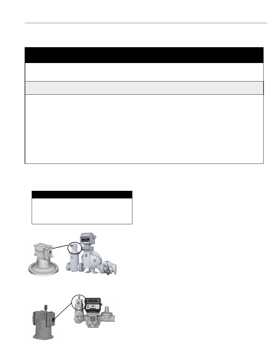
Bulk Plant Meter System
Truck Meter System
relieving Internal Pressure
All internal pressure must be relieved to zero pressure before disassembly or inspection of the strainer, vapor eliminator, any
valves in the system, the packing gland, and the front or rear covers.
!
WarnInG
relieving Internal Pressure Procedure for lPG and nh
3
Meters
6. Slowly crack the fitting on top of the differential valve to
relieve product pressure in the system. Product will drain
from the meter system.
7. As product is bleeding from the differential valve, slowly
reopen and close the valve/nozzle on the discharge line.
Repeat this step until the product stops draining from the
differential valve and discharge line valve/nozzle.
8. Leave the discharge line valve/nozzle open while working
on the system.
1. Close the belly valve of the supply tank.
2. Close the valve on the vapor return line.
3. Close the manual valve in the supply line on the inlet
side of the meter. If no manual valve exists on the inlet
side, consult the truck manufacturer for procedures to
depressurize the system.
4. Slowly open the valve/nozzle at the end of the supply
line.
5. After product has bled off, close the valve/nozzle at the
end of the supply line.
Serious injury or death from fire or explosion could result in performing maintenance on an
improperly depressurized and evacuated system.
In this manual, the term “
storage tank,” refers to any
type of receptacle meant to hold air or vapor expelled
by an air or vapor eliminator such as supply tanks,
spewage tanks, catch vessels, spit receptacles, etc.
“storage tank”