Packing gland ratio, Pattern codes – Liquid Controls Gear Plate Selection Guide User Manual
Page 4
4
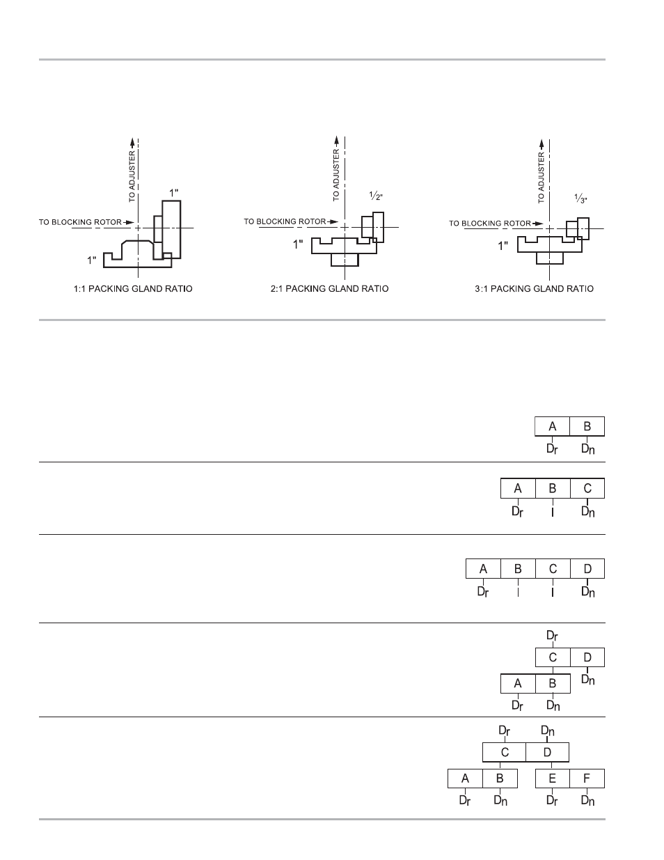
Pattern Codes
The Pattern Code number diagram shows five general gear assembly configurations that can be constructed using the
basic gear plate and swing arm assemblies. Patterns 10, 30, and 50 can be used with a mechanical temperature
compensator.
Dr=Driving gear, Dn=Driven gear, I=Idler gear
Pattern 10 - shows the simplest gear plate form with a driver and a driven gear. Total teeth of gear A
plus gear B must equal 118. (A=Dr, B=Dn)
Packing Gland Ratio
Three packing gland ratios are available to permit achieving the proper RPM of the register unit wheel (right hand wheel).
Pattern 20 - shows the simple gear plate form with an idler gear added to reverse output
rotation. Do not use when a mechanical temperature compensator is used.
(A=Dr, B=I, C=Dn)
Pattern 30 - shows a plate with dual idler gears. This pattern is used when a
Temperature Volume Compensator (TVC) is part of the register stack. When the register
stack includes a TVC, you must have an even number of centers in the gear plate.
When looking down on the Adjuster, rotation should be counterclockwise. (A=Dr, B=I,
C=I, D=Dn)
Pattern 40 - shows a plate with a compound gear set (B/C). Do not use when a mechanical
temperature compensator is used.
Pattern 50 - shows a plate with dual compound gears (B/C) and (D/E). This gear
plate configuration is used:
1.
When a TVC is part of the register stack, when the register stack includes a
TVC, you must have an even number of centers in the gear plate; when looking
down on the Adjuster, rotation should be counterclockwise.
2.
When you cannot obtain the desired ratio with only two sets of gears.