Rear panel description, Figure 5 - dc1 rear panel 6 – Lectrosonics DC1 User Manual
Page 7
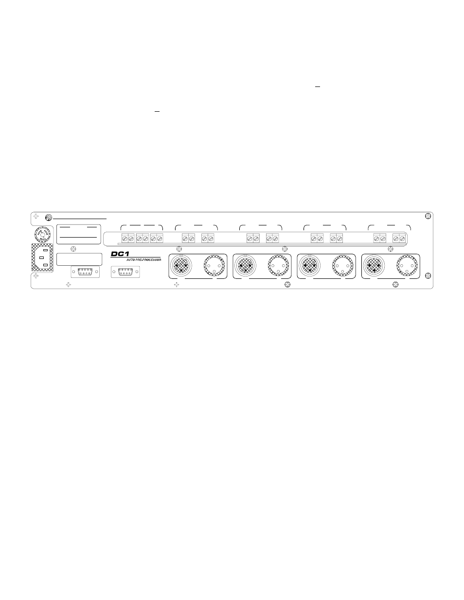
REAR PANEL DESCRIPTION
MICROPHONE INPUT - Accepts a balanced microphone signal. Fully balanced differential input, RF filtered, front
panel selectable 48 volt phantom supply. XLR type connector, Pin 2 is "+", Pin 3 is " ", and Pin 1 is ground.
MICROPHONE OUTPUT - Feeds the input of a standard mixing console. Transformer balanced, XLR type
connector, Pin 2 is "+", Pin 3 is " ", and Pin 1 is ground.
EXPANSION IN/OUT CONNECTORS - provide the capability for more than one DC1 to be used in an installation.
MEMORY PRESETS - Terminal connectors for remote triggering of programmed settings.
CH ON - Terminal connectors for individual channel overrides.
LOGIC - Terminal connectors for signals indicating channel activity. Allows connection to logic controlled devices
for speaker zoning, automated video switching, etc.
LECTROSONICS, INC.
CAUTION
TO REDUCE THE RISK OF FIRE
REPLACE ONLY WITH SAME TYPE
1/4 AMP, 250 VOLT FUSE
100/120V AC 50/60 HZ
30 WATTS
WARNING
TO REDUCE THE RISK
OF FIRE OR ELECTRIC SHOCK, DO
NOT EXPOSE THIS EQUIPMENT
TO RAIN OR MOISTURE
RIO RANCHO, NM - USA
EXPANSION OUT
EXPANSION IN
MEMORY PRESETS
1
2
3
-
+
-
+
-
+
-
+
-
+
CH. ON
LOGIC
OUT
IN
MADE IN USA
OUT
IN
CH 2
OUT
IN
CH 1
CH 4
OUT
IN
CH 3
CH 4
-
+
-
+
CH. ON
LOGIC
CH 3
-
+
-
+
CH. ON
LOGIC
CH 2
-
+
-
+
CH. ON
LOGIC
CH 1
Figure 5 - DC1 Rear Panel
6