Theory of operation, Channel 1 (channels 2-4 identical) – Lectrosonics DC1 User Manual
Page 3
THEORY OF OPERATION
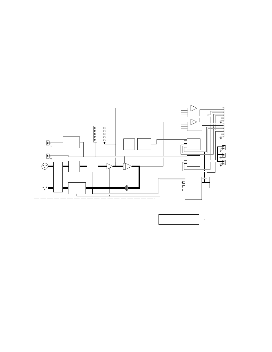
Please refer to the block diagram of the DC1 for the following discussion.
The DC1 has two major subsystems; the analog signal processing and the digital control section.
The audio signal processing includes an ultra-low noise microphone preamp, a high-quality Voltage Controlled
Amplifier (VCA), and an output transformer to prevent ground loops and RF interference. In addition, speech filters
and precision log amplifiers detect audio signals over a wide dynamic range. The headroom detection circuitry
monitors internal signal levels and gives a front panel indication of the amount of signal headroom left. The
attenuation detection circuitry monitors the control voltage to the VCA and gives a front panel indication of the
instantaneous gain reduction in the channel.
RFI
FILTER
FROM CHANNEL 2
FROM CHANNEL 3
FROM CHANNEL 4
FROM CHANNEL 4
FROM CHANNEL 3
FROM CHANNEL 2
TO CHANNEL 2
TO CHANNEL 3
TO CHANNEL 4
FRONT PANEL LEDS, LCD DISPLAY,
FROM CHANNEL 2
FROM CHANNEL 3
FROM CHANNEL 4
TO CHANNEL 4
TO CHANNEL 3
TO CHANNEL 2
SLAVE
MASTER
NC
NC
NC
NC
EXPANSION OUT
EXPANSION IN
CHANNEL 1
(CHANNELS 2-4 IDENTICAL)
BALANCED
INPUT
BALANCED
OUTPUT
LOGIC
OUTPUT
CHANNEL
ON
LOGIC OUT
PROCESSING
AND
OPTO-COUPLER
ATTENUATION
DISPLAY
HEADROOM
DISPLAY
PHANTOM
POWER
PROGRAMMABLE
MICROPHONE
PREAMP
VOLTAGE
CONTROLLED
AMPLIFIER (VCA)
RELAY
BYPASS
PROGRAMMABLE
ATTENUATOR
SPEECH
FILTER
LOG
CONVERTER
PRE-VCA
OUTPUT
POST-VCA
OUTPUT
11 CHANNEL
A/D
CONVERTER
8 CHANNEL
D/A
CONVERTER
NON-VOLATILE
MEMORY
uPROCESSOR
MC68HC705
PRE-VCA OUT
POST-VCA OUT
NOM OUT
VAR THRESHOLD
NOM TOTAL
EXT PRIORITY
GND
PRE-VCA IN
POST-VCA IN
NOM IN
VAR THRESHOLD
NOM TOTAL
EXT PRIORITY
GND
MEMORY
PRESET 1
MEMORY
PRESET 2
MEMORY
PRESET 3
AND PUSHBUTTONS
Figure 1 - DC1 Block Diagram
The heart of the digital control section consists of a Motorola 68HC705 micro-controller. The micro-controller is
interfaced to the LCD display and front panel buttons, internal analog-to-digital and digital-to-analog converters, and
relay drivers. The automatic mixing algorithm is completely software controlled, which provides a level of
performance difficult to obtain with purely analog systems.
The DC1 is a mic level in, mic level out device. The microphone preamp in each channel may be set (via front
panel control) to 40dB (Input Type: High) or 60dB (Input Type: Low) to accommodate all types of microphones. 48
volt phantom power is also available (via front panel control) on a per channel basis. After the signal is amplified, it
passes through the VCA. From there, the signal is buffered and transformer coupled to a passive attenuation
network, which brings the signal back down to mic level.
2