Front panel description, Figure 4 - dc1 front panel 5, Lectrosonics – Lectrosonics DC1 User Manual
Page 6
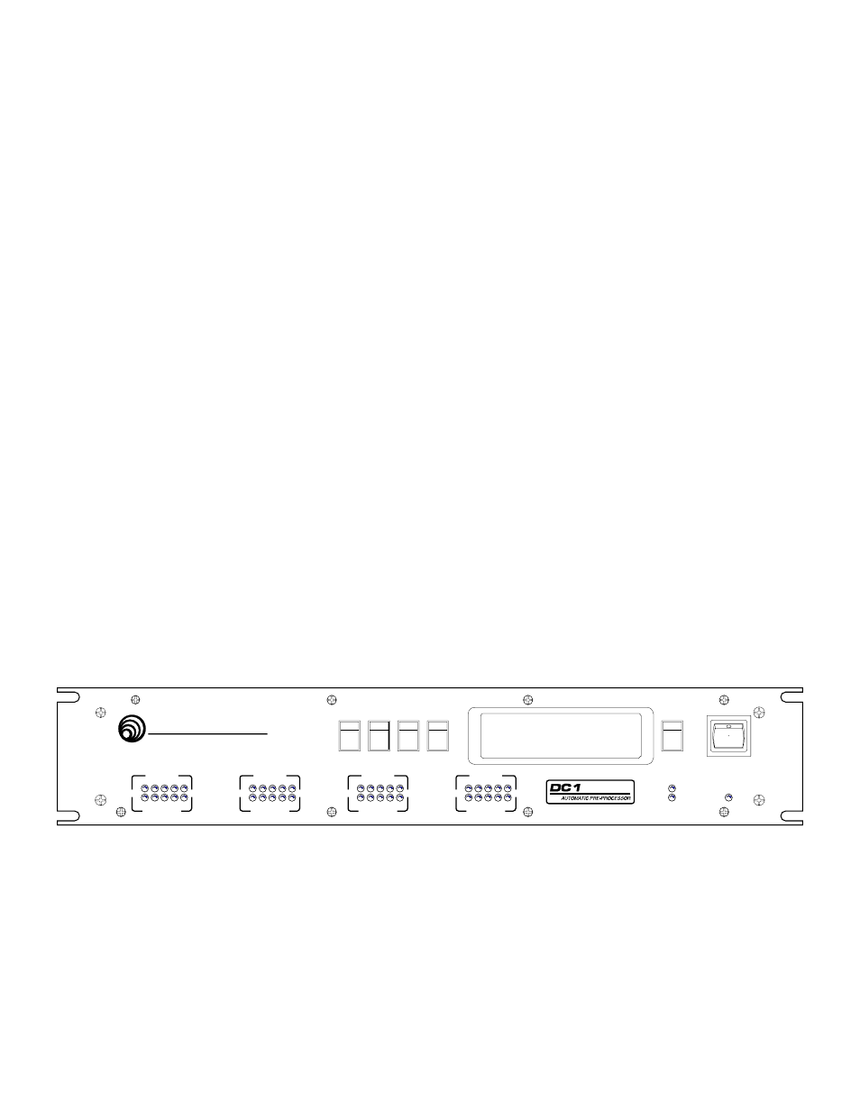
FRONT PANEL DESCRIPTION
HEADROOM LED METER - Indicates the instantaneous amount of headroom available in the channel. Internal
signals are monitored in each channel, and the Headroom LED meter shows the number of dB before channel
clipping occurs. Note that even with no signal, the "40dB" LED is lit, indicating at least 40dB of headroom.
ATTENUATION LED METER - Indicates the instantaneous amount of attenuation for each channel. Note that the
"20dB" LED is always lit, as the maximum channel attenuation under any circumstance is 20dB.
OPERATE LED - Indicates that the DC1 is in the Operate mode. In the Operate mode, no settings on the DC1
can be adjusted. Note that the Operate LED will flash when the DC1 is in the Bypass mode.
NEW SETTING LED - Indicates the DC1 is in the New Setting mode. In the New Setting mode, adjustments to the
settings on the DC1 can be made and stored as desired.
MODE PUSHBUTTON - Changes the operational mode of the DC1 between Operate, New Setting, and Bypass.
Note the a blinking cursor only appears on the LCD display in the New Setting mode. The blinking cursor is
another cue that changes can be made to DC1 settings. In the Bypass mode, the Operate LED flashes. If the
Mode button is pressed and held while the DC1 is powered up, the DC1 will enter a setup mode whereby the input
signal level of each channel will be displayed in real time. From this screen, access may be gained to the A
UTO
S
ET
function.
UP and DOWN PUSHBUTTONS - Allows the DC1 to be cycled through its function options, as well as enabling the
function values to be changed.
SELECT PUSHBUTTON - Selects the area on the LCD display for which the Up and Down pushbuttons are active.
The blinking cursor will be placed in the selected area. The first line of the display is the name of the selected
function. The second line of the display shows the selected channel, and also the current value of the selected
function.
SAVE PUSHBUTTON - Allows all the current values of DC1 functions to be saved to permanent memory.
POWER LED - Indicates the presence of AC power to the DC1.
POWER SWITCH - Turns the DC1 on or off.
LECTROSONICS
CH 1
DIGITAL CONTROL SERIES
HEADROOM
dB
ATTENUATION
40
30
20
10
0
20
15
10
5
0
CH 2
HEADROOM
dB
ATTENUATION
40
30
20
10
0
20
15
10
5
0
CH 3
HEADROOM
dB
ATTENUATION
40
30
20
10
0
20
15
10
5
0
CH 4
HEADROOM
dB
ATTENUATION
40
30
20
10
0
20
15
10
5
0
SAVE
SELECT
DOWN
UP
MODE
NEW SETTING
OPERATE
POWER
Figure 4 - DC1 Front Panel
5