Impulse 7204 User Manual
Page 7
Card
Setup
Sealevel Systems ULTRA 485+2.PCI Page
4
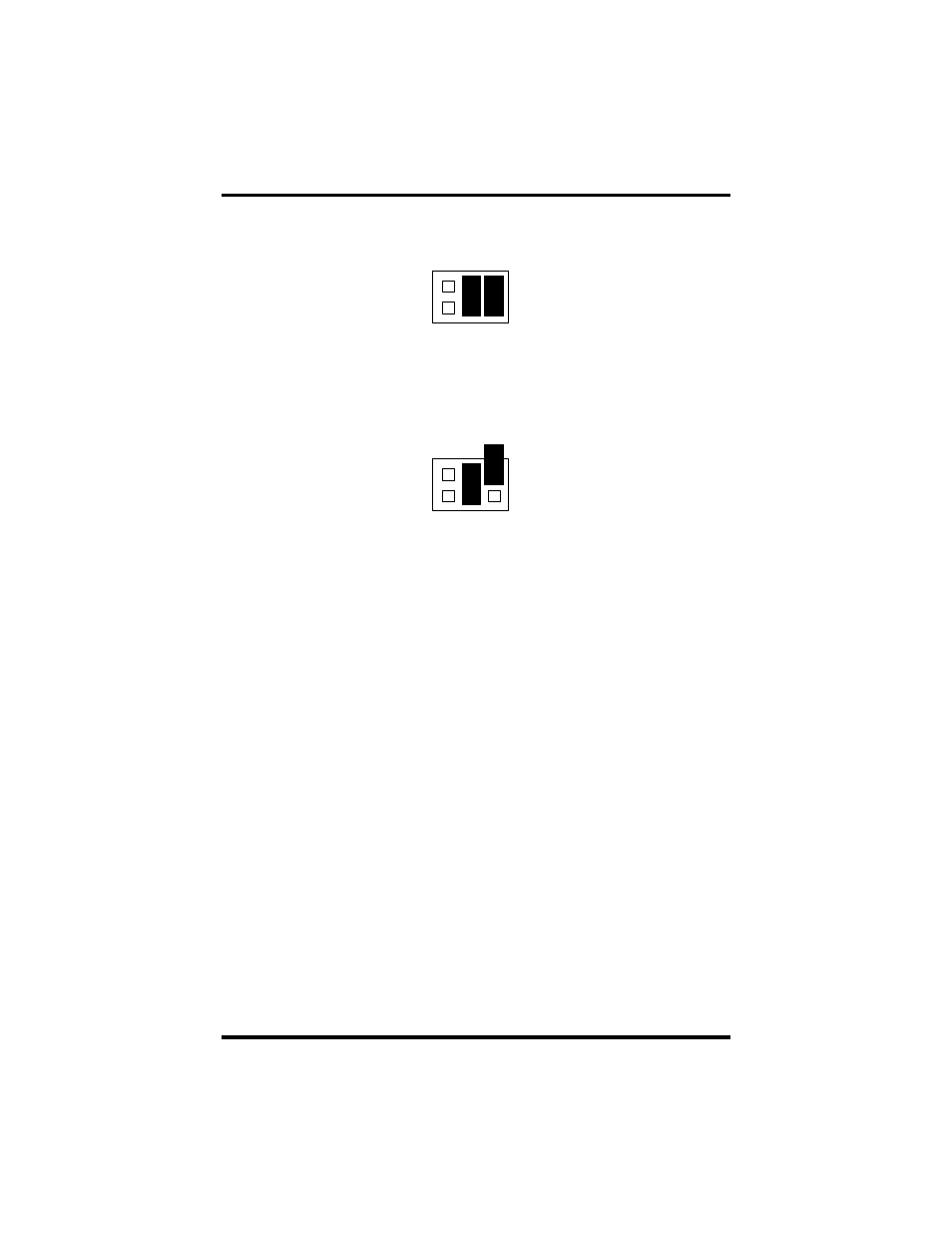
Interface Mode Examples J1B and J2B (continued)
AT
RT
NE
Figure 4 - Headers J1B and J2B, RS-485 ‘RTS’ Enabled, with ‘No Echo’
AT
RT
NE
Figure 5 - Headers J1B and J2B, RS-485 ‘RTS’ Enabled, with ‘Echo’
Address and IRQ selection
The ULTRA 485+2.PCI is automatically assigned I/O addresses and IRQs by
your motherboard BIOS. Only the I/O address may be modified by the user.
Adding or removing other hardware may change the assignment of I/O addresses
and IRQs.
See also other documents in the category Impulse Hardware:
- PCW-5181 (120 pages)
- PCM-4373 (2 pages)
- EPIC-5536 (2 pages)
- EPIC-CV07 (2 pages)
- EPIC-QM57 (2 pages)
- EPIC-QM77 (2 pages)
- VSX-6118-V2 (1 page)
- VSX-6116-V2 (1 page)
- VSX-6115-V2 (1 page)
- VSX-6114-V2 (1 page)
- VDX-6318RD (1 page)
- VDX-6316RD (1 page)
- VDX-6315RD (1 page)
- VDX-6314RD (1 page)
- PCM-5895 Rev. A (2 pages)
- PCM-8120 (2 pages)
- PCM-9562 (3 pages)
- VSX-6127-V2 (1 page)
- PCM-9375 (3 pages)
- GENE-5315W1 Rev. B (2 pages)
- GENE-5315 Rev. A (2 pages)
- VDX-6327RD (1 page)
- VDX-6328RD (1 page)
- VDX-6329RD (1 page)
- VDX-6326RD (1 page)
- PCM-9343 (3 pages)
- GENE-9655 (2 pages)
- PCM-9362 (2 pages)
- GENE-LN05W2 Rev. B (2 pages)
- PCM-9363 (3 pages)
- GENE-TC05W2 (2 pages)
- GENE-CV05W2 (2 pages)
- SBC-210 (1 page)
- GENE-QM57 (2 pages)
- GENE-QM67 (2 pages)
- GENE-QM77 Rev B (2 pages)
- GENE-QM77 Rev A (2 pages)
- GENE-QM87 (1 page)
- EL630-NR (2 pages)
- EL620-C (2 pages)
- SB601-C (2 pages)
- SB600-C (2 pages)
- SB630-CRM (2 pages)
- CL630-CRM (2 pages)
- DL631-C226 (2 pages)