Electrical characteristics – Impulse 3542 User Manual
Page 11
© Sealevel Systems, Inc.
- 9 -
SIO4-104.232 User Manual
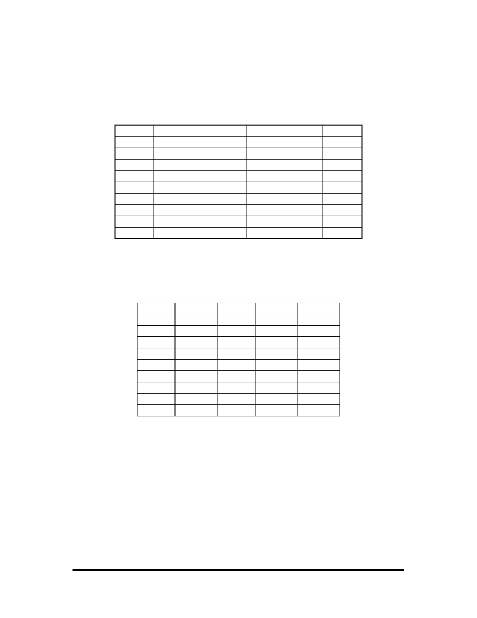
Available for use with the SIO4-104.232 are the CA228, the CA110/CA143, and the
CA222/TB10 combination cables. These cables terminate the SIO4-104.232 40-pin header to
four DB9M connectors. This termination provides the standard DB9 pin out for RS-232
(EIA/TIA574) in RS-232 mode. The following table illustrates the DB9 pin out when using any
of these optional cables.
Signal
Name
DB9 Male Pin #
Mode
GND Ground
5
TD Transmit
Data
3
Output
RTS Request
To
Send
7
Output
DTR
Data Terminal Ready
4
Output
RD Receive
Data
2
Input
CTS
Clear To Send
8
Input
DSR
Data Set Ready
6
Input
DCD
Data Carrier Detect
1
Input
RI Ring
Indicator
9
Input
Note: Please terminate any control signals that are not being used. The most common way to do
this is connect RTS to CTS and RI. Also, connect DCD to DTR and DSR. Terminating these
pins, if not used, will help ensure you get the best performance from your adapter.
If the CA143 is not used and the CA110 DB37 cable is used alone, the following pin-outs apply.
Port #
1
2
3
4
GND 33 14 24
5
TD 35 12 26 3
RTS 17 30 8 21
DTR 34 13 25
4
RD 36 11 27 2
CTS 16 31 7 22
DSR 18 29 9
20
DCD 37 10 28
1
RI 15 32 6 23