Impulse 3055 User Manual
Page 12
Card
Setup
Sealevel Systems ULTRA-485 Page
9
Line Termination
Typically, each end of the RS-485 bus must have line terminating resistors (RS-
422 terminates at the receive end only). A 100-ohm resistor is across each RS-
530/422/485 input in addition to a 1K ohm pull-up/pull-down combination that
biases the receiver inputs. DIP-switch SW2 provides the ability to customize this
interface to system requirements. Each switch position corresponds to a specific
portion of the interface. If multiple ULTRA 485 adapters are configured in a
RS-485 network, only the boards on each end should have switches T, P & P
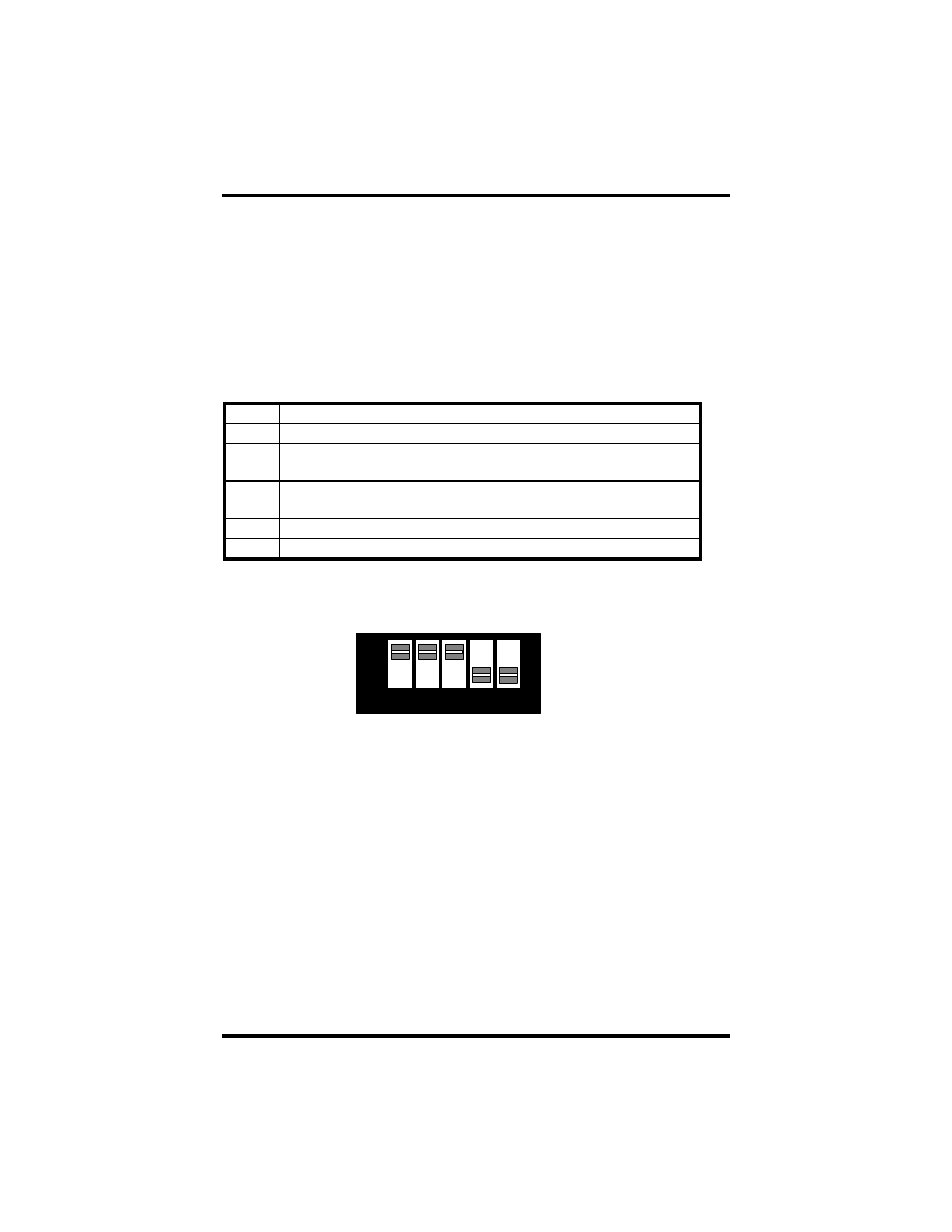
ON. Refer to the following table for each position’s operation:
Name Function
T
Adds or removes the 100 ohm termination.
P
Adds or removes the 1K ohm pull-down resistor in the
RS-422/RS-485 receiver circuit (Receive data only).
P
Adds or removes the 1K ohm pull-up resistor in the RS-422/RS-
485 receiver circuit (Receive data only).
L
Connects the TX+ to RX+ for RS-485 two-wire operation.
L
Connects the TX- to RX- for RS-485 two-wire operation.
Figure 8 - SW2, Line Termination
1 2 3 4 5
O N
O F F
T P P L L