Impulse 5103 User Manual
Page 5
Technical Description
Sealevel Systems ACB-MP.PCI Page
3
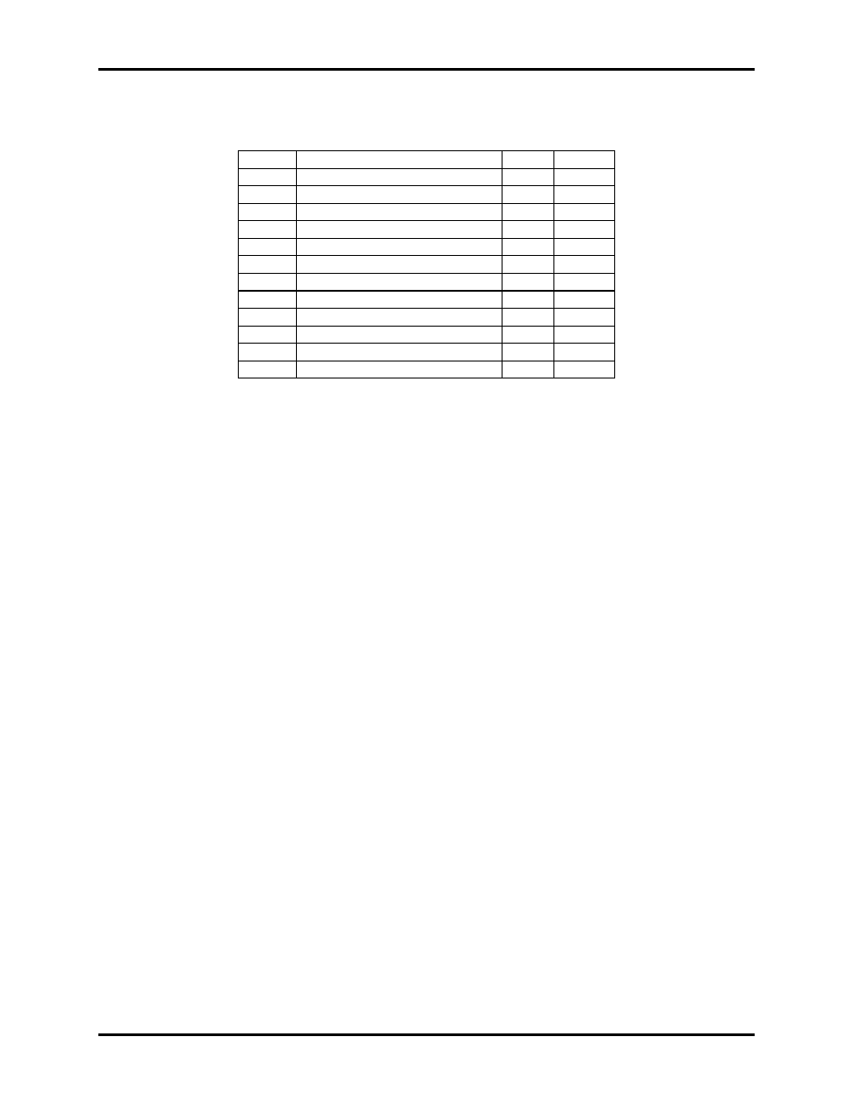
25 Pin Connector Signal Layouts (DB-25 Male)
RS-232 Signals
Signal Name
Pin
# Mode
GND Ground
7
RD Receive
Data
3 Input
CTS
Clear To Send
5
Input
DSR
Data Set Ready
6
Input
DCD
Data Carrier Detect
8
Input
TXC Transmit
Clock
15 Input
RXC Receive
Clock
17 Input
RI Ring
Indicator
22
Input
TSET
Transmit Signal Element Timing
24
Output
DTR
Data Terminal Ready
20
Output
TD Transmit
Data
2 Output
RTS
Request To Send
4
Output
RI- is
connected to Port B CTS on the 85230 and the enable bit is set in Base+6.
DSR- is connected to Port B DCD on the 85230 the enable bit is set in Base+6.
Technical Note: Please terminate any control signals that are not going to be used. The most common way to do this
is connect RTS to CTS and RI. Also, connect DCD to DTR and DSR. Terminating these pins, if not used, will help
insure you get the best performance from your adapter.