Impulse 8006 User Manual
Page 11
© Sealevel Systems, Inc.
- 9 -
ISO-16.PCI User Manual
Reading the Inputs
The inputs are active Low. If no voltage is applied across one of the differential
inputs it returns a one on that bit. If an AC or DC voltage (of sufficient magnitude,
covered above) is applied it returns a zero on that bit.
Function Available
Port
Address Hex
R A
Base
+
0
R B
Base
+
1
R = Read
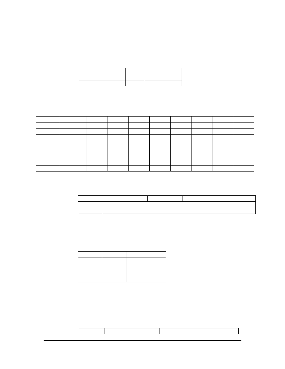
Register Description
Address Mode D7 D6 D5 D4 D3 D2 D1 D0
Base+0
R/W PAD7 PAD6 PAD5 PAD4 PAD3 PAD2 PAD1 PAD0
Base+1
R/W PBD7 PBD6 PBD5 PBD4 PBD3 PBD2 PBD1 PBD0
Base+2
R
{0} {0} {0} {0} {0} {0} {0} {0}
Base+3
R
{0} {0} {0} {0} {0} {0} {0} {0}
Base+4
R
{0} {0} {0} {0} {0} {0} {0} {0}
Base+5
R/W IRQEN
IRQST {0} {0} {0} {0} IRC1 IRC0
Base+6
R
{0} {0} {0} {0} {0} {0} {0} {0}
Base+7
R
{0} {0} {0} {0} {0} {0} {0} {0}
Interrupt Control
When enabled, interrupts are generated on Port A bit D0.
IRQEN
Interrupt enable
1 = enabled
0 = disabled ( 0 on power up )
IRC0
IRC1
Interrupt mode select, see table below
Interrupt mode select, see table below
Interrupt Mode Select Table
Interrupt source is Base+0 bit D0. When selecting the Interrupt Type, always disable
interrupts prior to changing or setting states. This will help prevent inadvertent or
unexpected interrupts from occurring.
IRC1 IRC0
Interrupt
Type
0 0 Low
Level
0 1
High
Level
1 0
Falling
Edge
1 1
Rising
Edge
Warning: When using the High and Low Level interrupts, an interrupt occurs when
input D0 changes to either a High or Low state. This will cause the computer to
remain in an interrupt state until the input state changes.
Interrupt Read
Reading the Interrupt Status port (Base+5) clears any interrupt pending.
IRQST
(D0) Interrupt Status
1 = interrupt pending, 0 = none