Impulse 8006 User Manual
Page 10
© Sealevel Systems, Inc.
- 8 -
ISO-16.PCI User Manual
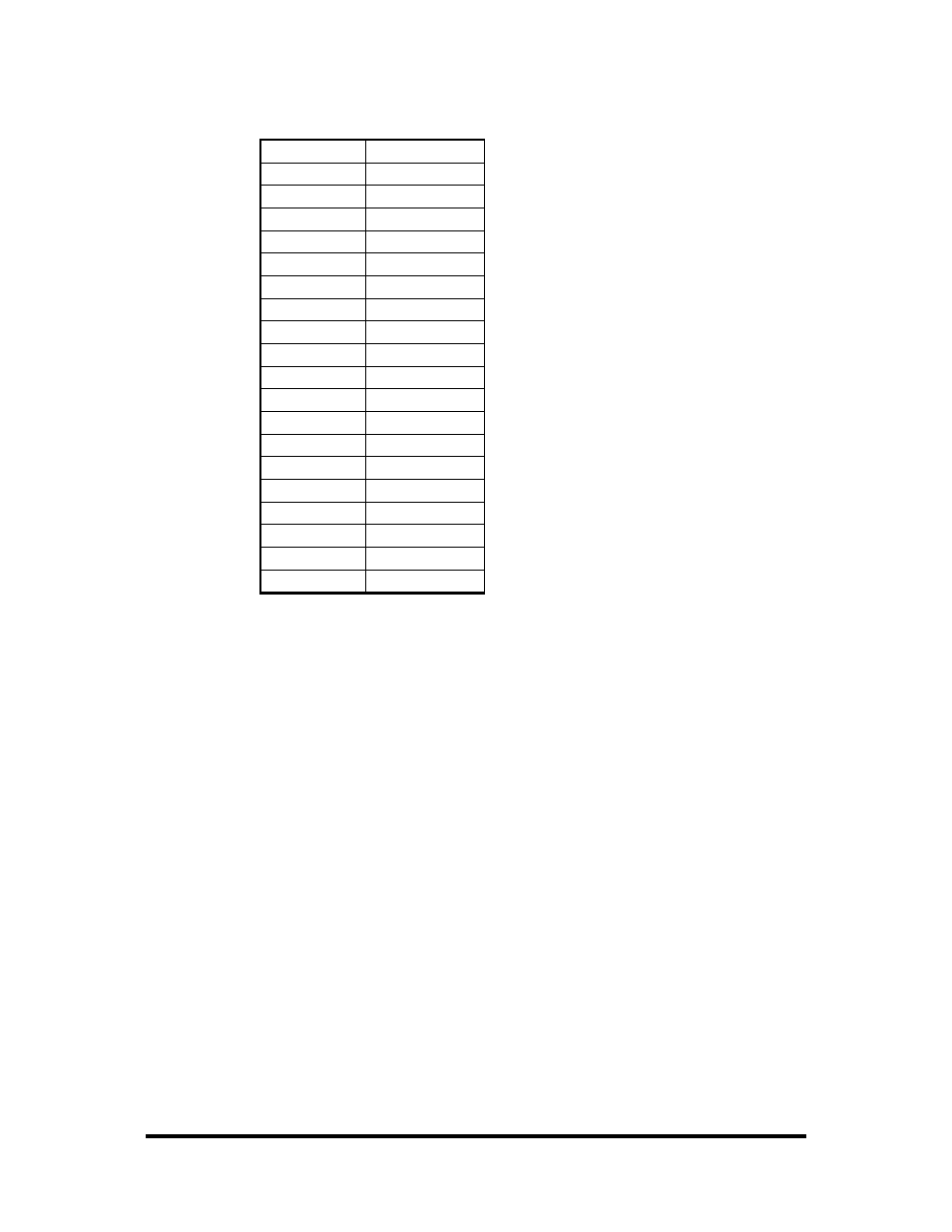
Pin Assignments
Port A Bit
P1
A0 18,37
A1 17,36
A2 16,35
A3 15,34
A4 14,33
A5 13,32
A6 12,31
A7 11,30
B0 10,29
B1 9,
28
B2 8,27
B3 7,26
B4 6,25
B5 5,24
B6 4,23
B7 3,22
Ground 2,20,21
+ 12 Volts
19
+ 5 Volts
1
Note: For ease in wiring, the card’s DB37 connector can be interfaced directly to the
Sealevel terminal block kit, Item# KT-101. This kit includes a 6’ Male/Female cable
(Item# CA112) and terminal block with screw terminals (Item# TB02) which
provides a simple means to connect field wiring to Sealevel DB37 I/O cards. The
TB02 provides both male and female DB37 connectors, eliminating the need for
gender benders and other adapters while simplifying cable connections.
Direct Hardware Control
In systems where the users program has direct access to the hardware (DOS) the
table below gives the mapping and functions that the ISO-16.PCI provide. The
address of each eight-bit port is calculated as shown in the table on the following
page, the cards base address plus an offset.