Impulse 3094 User Manual
Page 13
© Sealevel Systems, Inc.
- 11 -
ISO-16 User Manual
Relative Addressing vs. Absolute Addressing
The SeaIO API makes a distinction between “absolute” and “relative” addressing
modes. In absolute addressing mode, the Port argument to the API function acts as a
simple byte offset from the base I/O address of the device. For instance, Port #0
refers to the I/O address base + 0; Port #1 refers to the I/O address base + 1.
Relative addressing mode, on the other hand, refers to input and output ports in a
logical fashion. With a Port argument of 0 and an API function meant to output
data, the first (0
th
) output port on the device will be utilized. Likewise, with a Port
argument of 0 and an API function designed to input data, the first (0
th
) input port of
the device will be utilized.
In all addressing modes, port numbers are zero-indexed; that is, the first port is port
#0, the second port is #1, the third #2, and so on.
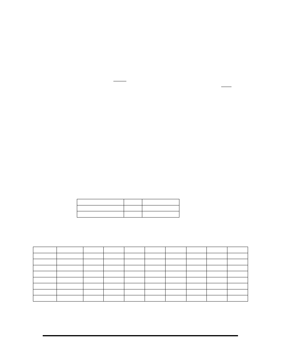
Direct Hardware Control
In systems where the users program has direct access to the hardware (DOS) the
table below gives the mapping and functions that the ISO-16 provide. The address of
each eight-bit port is calculated as shown in the table on the following page, the
cards base address plus an offset.
Reading the Inputs
The inputs are active Low. If no voltage is applied across one of the differential
inputs it returns a one on that bit. If an AC or DC voltage (of sufficient magnitude,
covered above) is applied it returns a zero on that bit.
Function Available
Port
Address Hex
R
A
Base + 0
R
B
Base + 1
R = Read
Register Description
Address
Mode D7 D6 D5 D4 D3 D2 D1 D0
Base+0
R/W PAD7 PAD6 PAD5 PAD4 PAD3 PAD2 PAD1 PAD0
Base+1
R/W PBD7 PBD6 PBD5 PBD4 PBD3 PBD2 PBD1 PBD0
Base+2
R {0} {0} {0} {0} {0} {0} {0} {0}
Base+3
R {0} {0} {0} {0} {0} {0} {0} {0}
Base+4
R {0} {0} {0} {0} {0} {0} {0} {0}
Base+5
R/W IRQEN
IRQST
{0} {0} {0} {0} IRC1
IRC0
Base+6
R {0} {0} {0} {0} {0} {0} {0} {0}
Base+7
R {0} {0} {0} {0} {0} {0} {0} {0}