Impulse 3096 User Manual
Page 14
© Sealevel Systems, Inc.
- 12 -
DIO-16 User Manual
Reading the Outputs
The relay ports return the ones complement of the value that is currently being used
to drive the relays.
Writing the Outputs
The output ports are the only ports that can be written. The relays on a standard
DIO-16 are normally open. To close a relay a one must be written to the appropriate
bit.
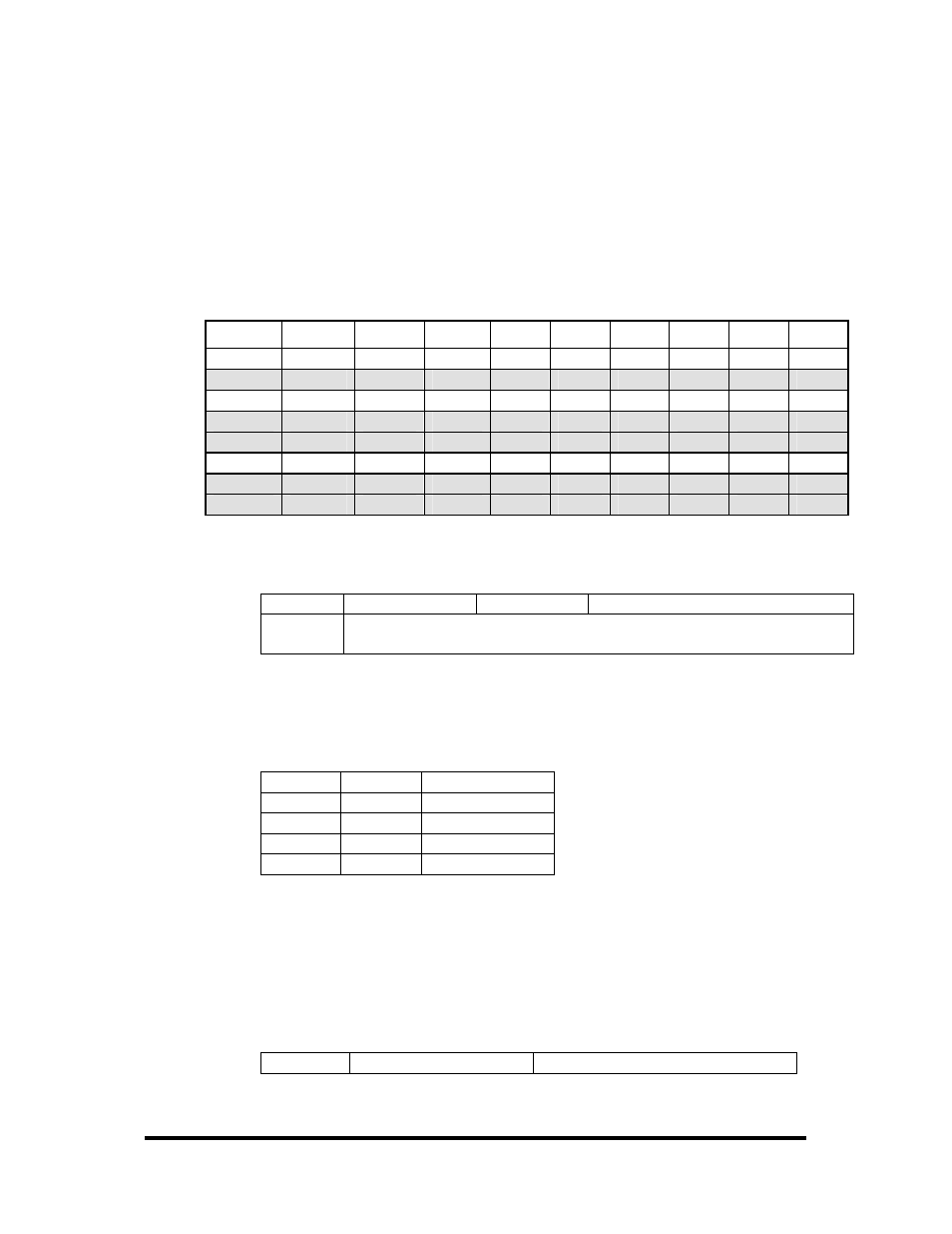
Register Description
All ports are set to input after reset or power up.
Address Mode D7
D6 D5 D4 D3 D2 D1 D0
Base+0
RD PAD7
PAD6
PAD5 PAD4 PAD3 PAD2 PAD1 PAD0
Base+1
RD
{0}
{0}
{0}
{0}
{0}
{0}
{0}
{0}
Base+2 RD/WR PCD7 PCD6 PCD5 PCD4 PCD3 PCD2 PCD1 PCD0
Base+3
RD
{0}
{0}
{0}
{0}
{0}
{0}
{0}
{0}
Base+4
RD
{0}
{0}
{0}
{0}
{0}
{0}
{0}
{0}
Base+5 RD/WR
IRQEN IRQST
{0} {0} {0} {0} IRC1
IRC0
Base+6
RD
{0}
{0}
{0}
{0}
{0}
{0}
{0}
{0}
Base+7
RD
{0}
{0}
{0}
{0}
{0}
{0}
{0}
{0}
Interrupt Control
When enabled, interrupts are generated on Port A bit D0.
IRQEN
Interrupt enable 1 = enabled
0 = disabled ( 0 on power up )
IRC0
IRC1
Interrupt mode select, see table below
Interrupt mode select, see table below
Interrupt Mode Select Table
Interrupt source is Base+0 bit D0. When selecting the Interrupt Type, always disable
interrupts prior to changing or setting states. This will help prevent inadvertent or
unexpected interrupts from occurring.
IRC1 IRC0 Interrupt
Type
0 0 Low
Level
0 1 High
Level
1 0
Falling
Edge
1 1
Rising
Edge
Warning: When using the High and Low Level interrupts, an interrupt occurs when
input D0 changes to either a High or Low state. This will cause the computer to
remain in an interrupt state until the input state changes.
Interrupt Read
Reading the Interrupt Status port (Base+5) clears any interrupt pending.
IRQST
(D0) Interrupt Status
1 = interrupt pending, 0 = none