Impulse 8012 User Manual
Page 11
© Sealevel Systems, Inc.
- 9 -
DIO-16.LPCI User Manual
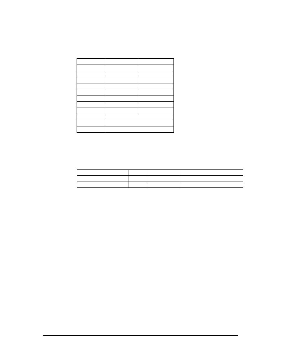
DB-37 Male Pin Assignment
Via optional DB-44 Male to DB-37 Male 6’ cable, Part Number CA206
Bit
Port A Pins
Port C Pins
0 2,20 10,28
1 3,21 11,29
2 4,22 12,30
3 5,23 13,31
4 6,24 14,32
5 7,25 15,33
6 8,26 16,34
7 9,27 17,35
GND 18,36,37
+12V 1
+5V 19
Direct Hardware Control
In systems where the users program has direct access to the hardware (DOS) the
tables that follow give the mapping and functions that the DIO-16.LPCI provides.
Function Available
Port
Address Hex
Port Type
RD
A
Base + 0
Optically Isolated Input Port
RD/WR
C
Base + 2
Reed Relay Output Port
RD = Read, RD/WR = Read or Write
Reading the Inputs
The inputs are active Low. If no voltage is applied across one of the differential
inputs it returns a one on that bit. If an AC or DC voltage is applied it returns a zero
on that bit.
Reading the Outputs
The relay ports return the ones complement of the value that is currently being used
to drive the relays. When using the API the actual value is returned not the
complement of the value.
Writing the Outputs
The output ports are the only ports that can be written. The relays on a standard
DIO-16.LPCI are normally open. To close a relay a one must be written to the
appropriate bit.