Card setup, Software installation – Impulse DIO-104.OPTO (3730) User Manual
Page 5
© Sealevel Systems, Inc.
- 3 -
DIO-104.OPTO User Manual
Card Setup
Address Selection
The DIO-104.OPTO occupies 4 consecutive I/O locations. The DIP-switch (S1) is
used to set the base address for these locations. Be careful when selecting the base
address as some selections conflict with existing PC ports. The following table
shows several examples that usually do not cause a conflict. Even though four I/O
addresses are decoded, only the first two are actually used, the other two ports are to
maintain compatibility with existing Sealevel Systems adapters.
Address Binary
Switch
Settings
A9 A8 A7 A6 A5 A4 A3 A2
1 2 3 4 5 6 7 8
100-103 01
0000
00xx
On Off
On On On On On On
104-107 01
0000
01xx
On Off
On On On On On Off
200-203 10
0000
00xx
Off
On On On On On On On
280-283 10
1000
00xx
Off
On Off
On On On On On
284-287 10
1000
01xx
Off
On Off
On On On On Off
2EC-2EF 10
1110
11xx
Off
On Off
Off
Off
On Off Off
300-303 11
0000
00xx
Off
Off
On On On On On On
320-323 11
0010
00xx
Off
Off
On On Off
On On On
388-38B 11
1000
10xx
Off
Off
Off
On On On Off On
3A0-3A3 11
1010
00xx
Off
Off
Off
On Off
On On On
3A4-3A7 11
1010
01xx
Off
Off
Off
On Off
On On Off
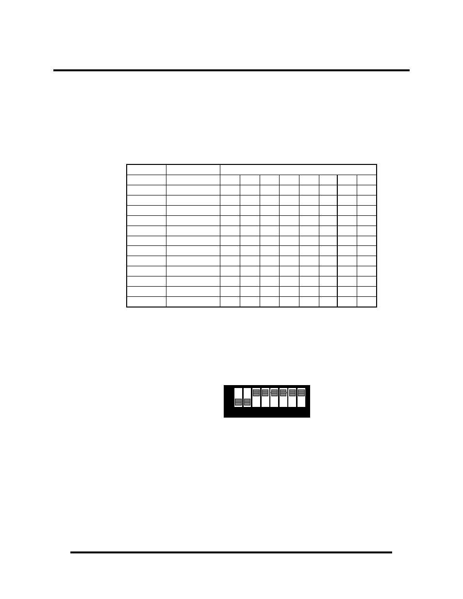
The following illustration shows the correlation between the DIP-switch setting and
the address bits used to determine the base address. In the example below, address
300 is selected as the base address. Address 300 in binary is XX 11 0000 00XX
where X = a non-selectable address bit.
1 2 3 4 5 6 7
ON
OFF
A9
A2
8
Note: Setting the switch ‘On’ or ‘Closed’ corresponds to a ‘0’ in the address, while
leaving it ‘Off’ or ‘Open’ corresponds to a ‘1’.