Wiring devices to the axb-232, Preparing captive wires, Wiring guidelines – AMX AXlink Bus Controllers AXB-232++ User Manual
Page 10: Using axlink, Using axlink and external power supply
Installation and Wiring
6
AXB-232++ RS-232/422/485 Interface
Wiring Devices to the AXB-232++
Preparing captive wires
To connect the wiring into a captive-wire connector:
1.
Strip 1/4 inch off the wire insulation for all four wires.
2.
Tin 2/3 of the exposed wire.
3.
Insert each wire into the appropriate captive-wire connector up to the insulation.
4.
Tighten the captive screws to secure the fit in the connector.
Wiring guidelines
The interface requires a 12 VDC power to operate properly. The interface uses a PSN2.8 power
supply. The Central Controller supplies power via the AXlink cable or external 12 VDC power
supply. The maximum wiring distance between the Central Controller and interface is determined
by power consumption, supplied voltage, and the wire gauge used for the cable. The table below
lists wire sizes and maximum lengths allowable between the AXB-RS232++ and Central
Controller. The maximum wiring lengths for using AXlink power are based on a minimum of 13.5
volts available at the Central Controller’s power supply.
Using AXlink
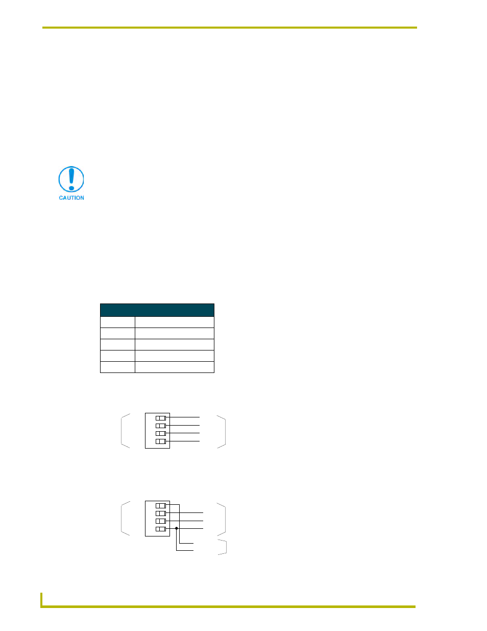
Connect the AXlink wiring to the connector on the AXB-232++ as shown in FIG. 4.
Using AXlink and External Power Supply
Connect the AXlink and power wiring to the connector on the AXB-232++ as shown in FIG. 5.
If the device is using a separate power supply, do not connect the power wiring from
the AXB-232++ to that device.
Wiring Guidelines at 160 mA
Wire Size
Maximum Wiring Length
18 AWG
733.57 feet (223.59 m)
20 AWG
464.11 feet (141.46 m)
22 AWG
289.35 feet (88.19 m)
24 AWG
182.39 feet (55.59 m)
FIG. 4 AXlink bus and +12 VDC power wiring
FIG. 5 AXlink bus and +12 VDC power wiring
PWR
AXP
AXM
GND
AXlink
System
PWR
AXP
AXM
GND
PWR
AXP
AXM
GND
+12 VDC
GND
AXlink
System
Power Supply
PWR
AXP
AXM
GND