Installation specifications warning – Controlled Products Systems Group RAM5000 User Manual
Page 8
6
RAMSET
www.ramsetinc.com
RAM 5000 • 5100 • 5200
TOP vIEW
GATE
ShOWN OPEN
Lh
FRONT
INSTALLATION
Wall
GATE
4”
MIN
4”
24”
4”
MIN
4”
6 1/2”
6 1/2”
5”
GATE
WALL
Conduit for
Master-Slave
Conduit for
power
Conduit for low
voltage wires
24” x 24” x 24”
Concrete Pad
GATE
6”
11”
12 1/4”
BASE
OPERATOR
concrete
24”
concrete
24”
24”
TAIL
5”
7 5/8”
4”
TOP vIEW
GATE ShOWN CLOSED
Lh
FRONT INSTALLATION
CL
Mark centers and
install four 1/2-13
UNC Red-head
Anchor Bolts
Wall
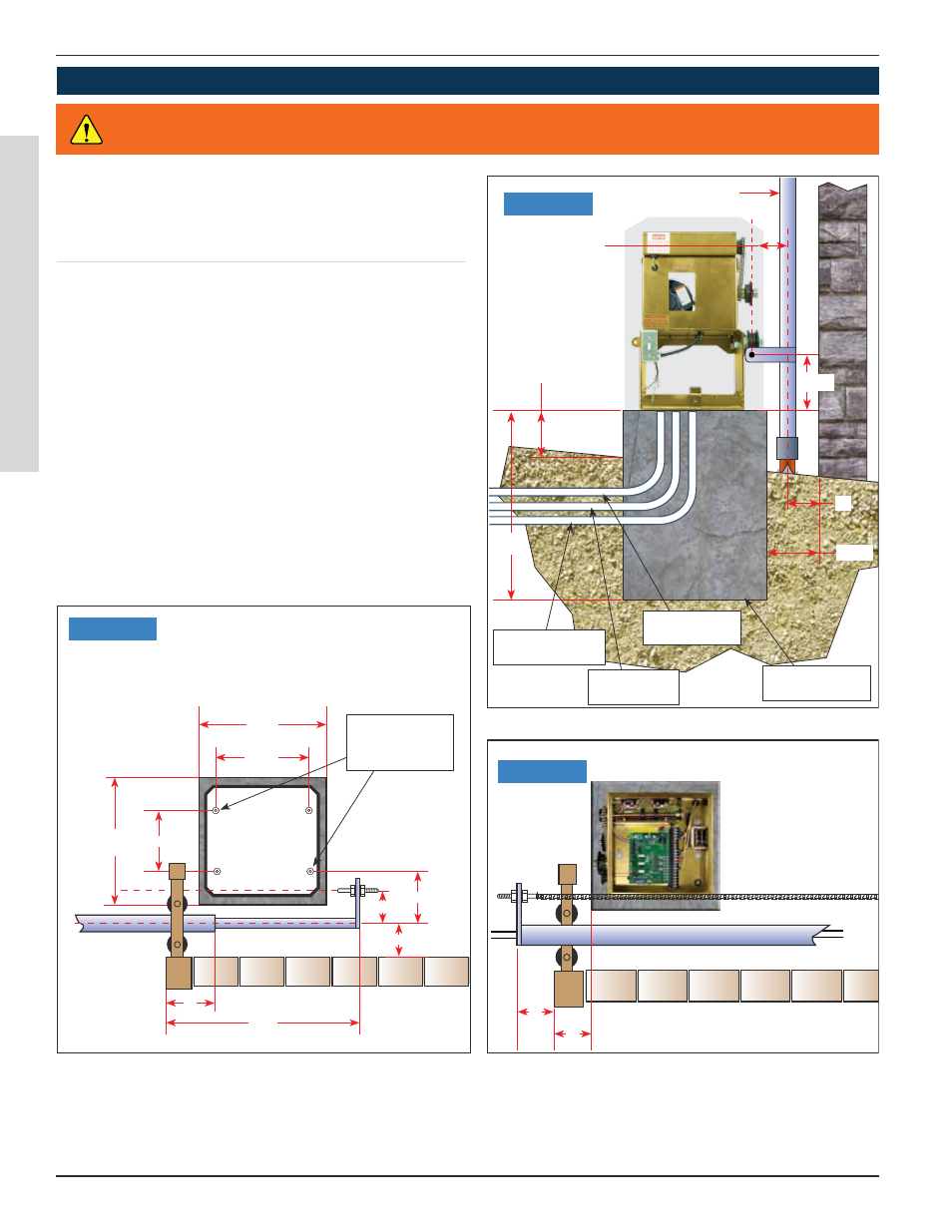
CONCRETE PAD CONSTRUCTION
Dimensions given for the pad are based on soil bear-
ing shear of 2000 P.S.F. These figures may have to
be adjusted depending on local soil conditions.
1. Construct form for mounting pad according to
dimensions shown in Figure 1, 2 and 3.
2. Locate mounting pad according to dimensions
given in illustration.
3. Level top edge of form.
4. Set reinforcing bars and wire mesh.
5. Mix concrete, pour mixture into form. Level and
finish surface after pouring is complete.
6. Allow pad to cure for 48 hours, and remove forms.
Figure 1
Figure 2
Figure 3
All Sliding Gate Operators are factory preset
for (LH) Left Hand Installations.
INSTALLATION SPECIFICATIONS
WARNING
Do not exceed the specifications. The warranty on your unit will be void if the
installation exceeds the recommended specifications.