Dip switch configuration, Dip switch “a” dip switch “b – Controlled Products Systems Group RAM5000 User Manual
Page 12
10
RAMSET
www.ramsetinc.com
RAM 5000 • 5100 • 5200
Dip Switch “A”
Dip Switch “B”
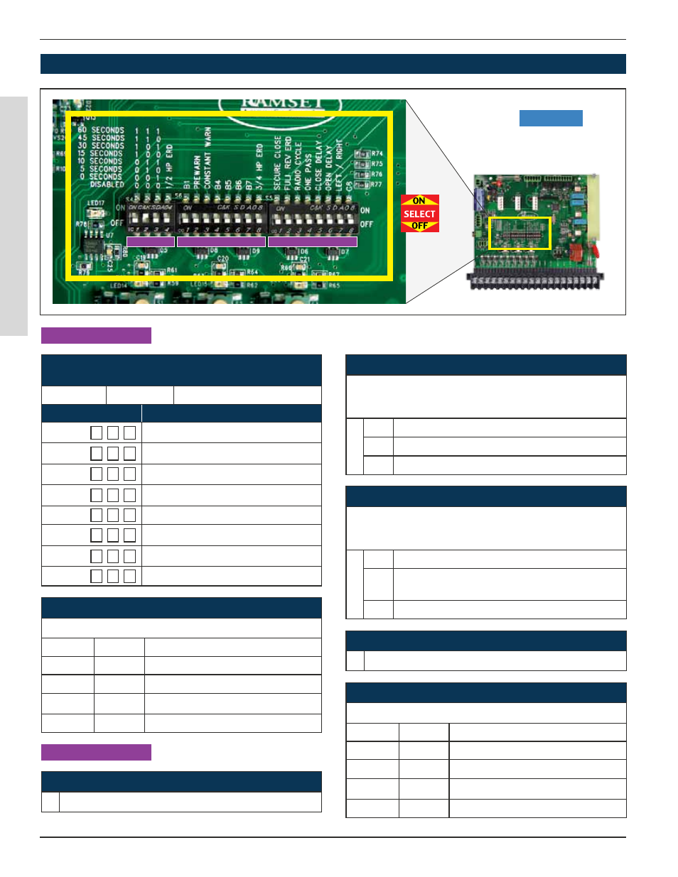
Dip Switch “C”
“Intelligate” Control Board
DIP SWITCh CONFIGURATION
Figure 11
DIP SWITCH “A”
DIP SWITCH “B”
Dip Switch “A” 4 - 1/2 hP ERD
Dip switch A4 works with Dip switch B8
DIP A4
B8
Sensitivity
OFF
OFF
Most Sensitive
ON
OFF
1/2 Hp — Medium Sensitivity
OFF
ON
3/4 Hp — Medium Sensitivity
ON
ON
Least Sensitive
Dip Switch “B” 8 - 3/4 hP ERD
Dip switch B8 works with Dip switch A4
DIP A4
B8
Sensitivity
OFF
OFF
Most Sensitive
ON
OFF
1/2 Hp — Medium Sensitivity
OFF
ON
3/4 Hp — Medium Sensitivity
ON
ON
Least Sensitive
Dip Switch “B” 2; “PRE WARN”
Used with jP2 “Relay Connections”: pins 7 & 8.
Triggers a relay, for an alarm or light (not included), for 3 sec-
onds before the gate will move in any direction.
Sw.
Function:
ON Triggers the relay on jP2 pins 7 & 8 for 3 seconds.
OFF Regular working conditions
Dip Switch “B” 3; “CONSTANT WARN”
Used with jP2 “Relay Connections”: pins 7 & 8.
Triggers a relay, for an alarm or light (not included), to be ac-
tive anytime the gate is in motion.
Sw.
Function:
ON Triggers the relay on jP2 pins 7 & 8 while the gate
is moving
OFF Regular working conditions
Dip Switch “B” 1; Not in use at this time.
Leave in the ‘Off’ position.
Dip Switch “B” 4,5,6 & 7; Not in use at this time.
Leave in the ‘Off’ position.
Dip Switch “A” 1, 2 & 3;
AUTOMATIC TIMER TO CLOSE GATE
‘0’ is “OFF”
‘1’ is “ON”
Switch 1 2 3
Gate Open Duration:
1 1 1
60 seconds
1 1 0
45 seconds
1 0 1
30 seconds
1 0 0
15 seconds
0 1 1
10 seconds
0 1 0
05 seconds
0 0 1
00 seconds
0 0 0
Disabled - command required to close