Loop sensor installation gate travel adjustment – Controlled Products Systems Group RAM5000 User Manual
Page 10
8
RAMSET
www.ramsetinc.com
RAM 5000 • 5100 • 5200
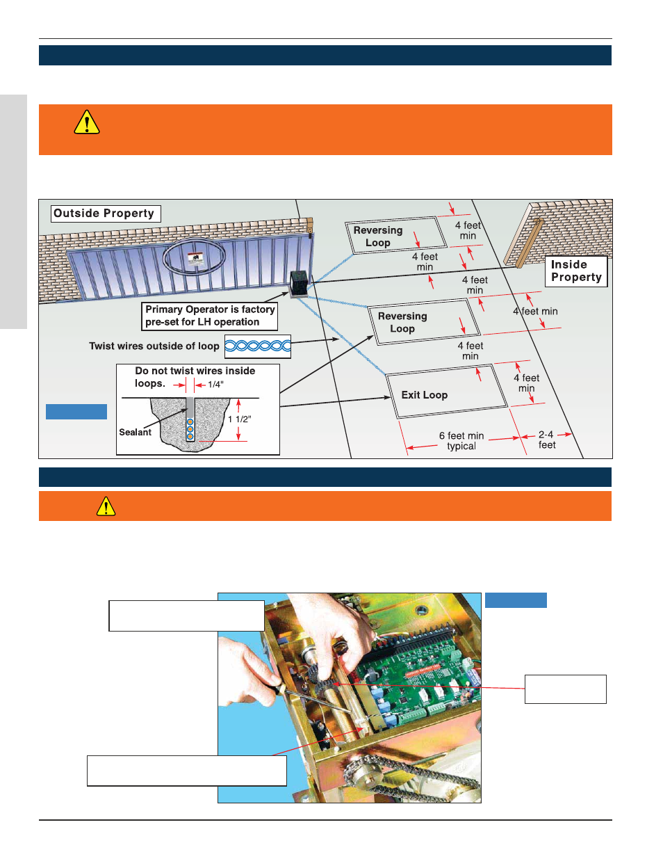
LOOP SENSOR INSTALLATION
GATE TRAvEL ADJUSTMENT
Reversing Loops on the ground floor, prevents gate from closing when vehicle is in loop area.
Exit Loops on the ground floor, opens gate when vehicle crosses loop area.
To adjust gate travel, depress spring loaded bracket and spin each Adjustment Nut to the required posi-
tion (Figure 8). L.E.D. must turn on to indicate position open or close when limit switch is activated by limit
switch adjustment nut.
Figure 7
Figure 8
A non-contact sensor (photoelectric sensor or equivalent) and a contact sensor (edge
device or equivalent) is required on each individual installation to comply with UL325.
WARNING
Ramset Gate Operators should always be installed with non-contact sensing devices such as
Loop Detectors, Photo Eyes or the equivalent.
Adjustment
Nuts
Depress spring loaded bracket
to free adjustment nuts
Turn Adjustment Nuts
with fingers
WARNING: TURN POWER OFF BEFORE ATTEMPTING ADJUSTMENT