Controlled Products Systems Group NT-T5-ETLDUAL User Manual
Page 17
17
17
Board
Harness
Function
Pin 1
Orange
Open Limit
Pin 2
White
Close Limit
Pin 3
Black
Motor (positive on open, negative on close)
Pin 4
Red
Motor (negative on open, positive on close)
Pin 5
Green
Common for both limit switches
Pin 6
Yellow
Encoder Input from EIB module
Pin 7
Black
Battery Negative
Pin 8
Red
Battery Positive
1
3
5
7
2
4
6
8
Master/Slave Connector
Applies battery voltage directly to motor to open gate (will not close gate) if
control board fails. User must unplug before gate opens to maximum travel or
the 15 amp fuse will open. Fuse should be checked before returning gate to
service.
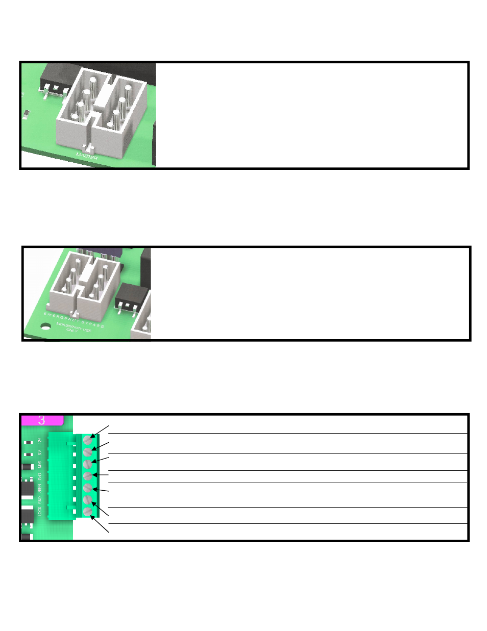
EMERGENCY BYPASS
12V
Supplied battery voltage
SLV
Slave Operator Indicator (indicates slave side of gate is closed)
+12V when on closed limit. Ground when off of closed limit.
MAS
Master Operator Indicator (indicates master side of gate is closed)
+12V when on closed limit. Ground when off of closed limit.
GND
Battery supplied ground (connects to GND on EIB module)
SIREN
Connect to siren + (also connects to +12V on EIB module)
applies +12V when gate(s) are running, or in hard shutdown
GND
Battery supplied ground
LOCK
Connect to lock + (optional) Magnetic or Solenoid type locks (Dip Switch #6 Selectable)
Remote Outputs