Multiple safety devices connections, Wire nut, Safety wire connections – Controlled Products Systems Group OH200 User Manual
Page 15: Terminal strip
O
N
O
N
5
1
4
5
1
4
G
D
E
G
D
E
O
N
O
N
5
1
4
5
1
4
G
D
E
G
D
E
O
N
O
N
5
1
4
5
1
4
G
D
E
G
D
E
O
N
O
N
5
1
4
5
1
4
G
D
E
G
D
E
O
N
O
N
5
1
4
5
1
4
G
D
E
G
D
E
O
N
O
N
5
1
4
5
1
4
G
D
E
G
D
E
O
N
O
N
5
1
4
5
1
4
G
D
E
G
D
E
Power
Power
Detect
Detect
Loop Fail
Loop Fail
Reset
Reset
2
2
1
1
0
0
0
0
SENS.
SENS.
LEVEL
LEVEL
BOOST ON
BOOST ON
PULSE
PULSE
FREQ.
FREQ.
0
0
0
0
OFF
OFF
PRES
PRES
2
2
1
1
11
22
33
44
55
66
SAFETY Loop
detector
PHOTO
Beam
Relay (COM)
Relay (COM)
Relay (N.C.)
Relay (N.C.)
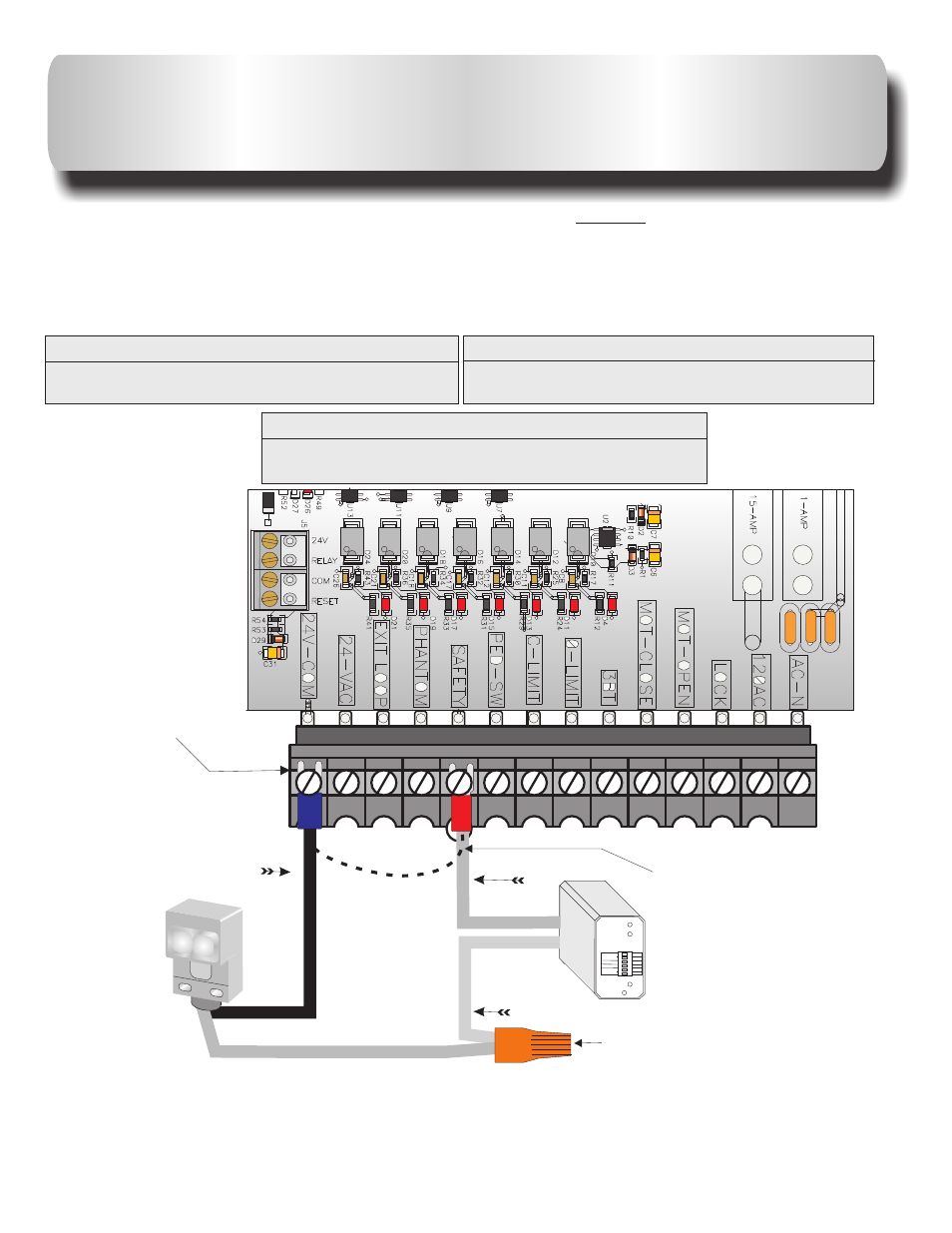
MULTIPLE SAFETY DEVICES
CONNECTIONS
Multiple
devices installed together must be connected in series .
the normally closed
(N.C.) dry contact from
accessory relay.
efore installing the accessory devices, remove
the black wire jumper from the
terminal position
SAFETY
“
”
SAFETY
Locate
each
Also, b
on the terminal strip of the control board.
From Accessory #1 to Terminal Strip
Relay Com to 24V-COM
From Accessory #2 to Terminal Strip
Relay N.C. to SAFETY
From Accessory #1 to Accessory # 2
Relay N.C. To Relay Com
This diagram is for the relay wires of the safety devices, two wires to the terminal
strip (one from each device) and two wires to the orange wire nut.
Wire nut
Terminal strip
Safety wire connections
14
AB
Remove black jumper
from SAFETY when
a safety device is
installed.