Operator setup, Operator mounting, Controller connection – Controlled Products Systems Group LRA User Manual
Page 7
LRA Linear Residential Actuator Installation Guide
- 5 -
228158 Revision X17 8-11-2011
Operator Setup
Operator Mounting
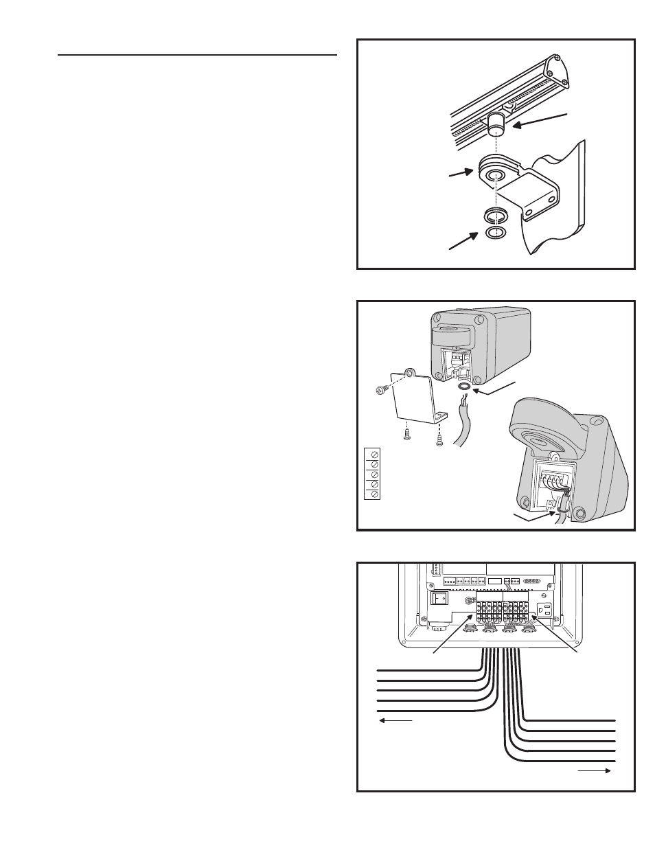
The operator mounts on the post bracket pin and into the
gate bracket bushing. Refer to Figure 5.
1. With the gate closed, carefully position the operator over the mounting
brackets.
2. Lower the operator onto the post bracket pin while guiding the
operator’s worm drive traveler shaft into the gate bracket bushing.
3. Install the washer and clip-ring on the post bracket pin.
4. Install the washer and clip-ring on the traveler shaft.
Controller Connection
The APeX Controller is mounted in a sealed NEMA4
enclosure. Open the cover for installation access.
The Controller contains two 5-position plug-in terminal
blocks for connection to one or two LRA operators. Terminal
block MOTOR-1 is used in single gate LRA installations.
Terminal block MOTOR-2 is used for the second arm in dual
gate LRA2 installations.
To make wiring easy, the terminal blocks are removable and
plug into the Controller’s circuit board.
1. Route the operator cable up through the fl uid-tight strain-relief fi tting
on the bottom of the Controller’s cabinet.
2. Noting the wire colors, connect the operator cable to MOTOR-1
Terminals 1-5 on the Controller.
3. Route the cable towards the operator. Be sure to leave enough slack
in the cable to allow for the gate swing.
4. Remove the operator’s wiring access plate (see Figure 6).
5. Cut the cable to length if required, then slide the O-ring over the end
of the cable.
6. Connect the interface cable to the operator’s terminal block matching
the same colors and terminal numbers used in Step 2 (see Figure 6).
7. Replace the operator’s wiring access plate being careful to align the
O-ring below the cable clamp. The O-ring helps keep out moisture.
For dual gate installations, repeat Steps 1-7 and connect the
second operator’s cable to the MOTOR-2 5-position terminal
block in the Controller (see Figure 7). Use the strain-relief
fi tting that comes with the LRA2 kit where the cable enters
the Controller cabinet.
TRAVELER
SHAFT
GATE BRACKET
BUSHING
WASHER
AND CLIP-RING
Figure 5. Mounting the Operator
Figure 6. Operator Cable Connections
Figure 7. Controller Cable Connections
12
3
45
5 - OPEN LIMIT
4 - COMMON (LIMIT)
3 - CLOSE LIMIT
2 - MOTOR
1 - MOTOR
MATCH TERMINAL NUMBERS
ON OPERATOR & CONTROLLER
PUT O-RING ON CABLE TO
SEAL OUT MOISTURE
O-RING
FITS
IN SLOT
MOTOR 1 TERMINALS
MOTOR 2 TERMINALS
TO LRA ARM #1
TO LRA ARM #2
1
2
3
4
5
5
4
3
2
1
FOR STAGGERED GATE INSTALLATIONS,
ONLY THE MOTOR 1 CONNECTION CAN BE
DELAYED ON OPENING. PLUG THE ARM TO
BE DELAYED INTO THE MOTOR 1 TERMINALS.
MOTOR 1
MOTOR 2
1
2 3 4 5 1 2 3 4 5