Pull-to-open bracket mounting instructions – Controlled Products Systems Group LA400 User Manual
Page 9
9
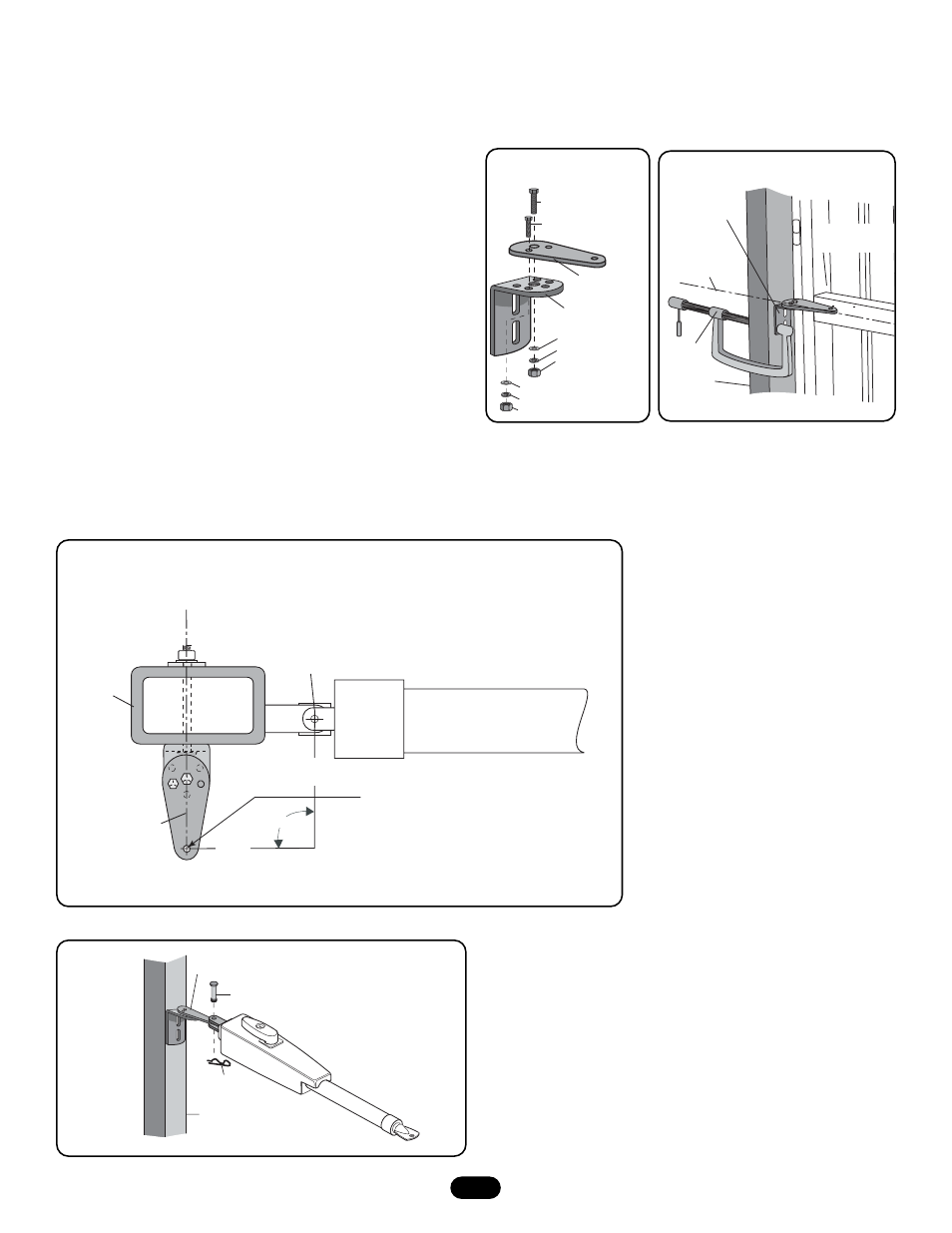
Post Bracket
Assembly
C Clamp
Fence
Post
Gate In
OPEN Position
Vertical Center
of Gate
Cross Member
3/8" Hex Bolt
3/8" Washer
3/8" Lock Washer
3/8" Nut
Pull-to-Open
Bracket
Post Bracket
5/16" Washer
5/16" Lock Washer
5/16" Nut
5/16" Hex Bolt
Center of Gate Hinge
PULL-TO-OPEN INSTALLATION
Gate Post
Closed Gate
7-3/4"
(19.7 cm)
7-3/4"
(19.7 cm)
NOTE: You may want to drive a stake in
the ground to help locate this point.
Bracket must
be straight
90°
Figure 2
Figure 3
NOTE: The mounting illustrations represent a typical installation using the provided gate hardware. The gate opener may also be installed by
welding it to the gate structure. For push-to-open installation order accessory kit 50-19503.
Figure 1
1. Place pull-to-open bracket on top of the post bracket. Insert 3/8"
hex bolt through middle hole and secure with lock washer, flat
washer and nut. Insert 5/16" hex bolt through hole in pull-to-open
bracket and post bracket. Secure with washer, lock washer and nut
(Figure 1.)
NOTE: Do not pivot bracket, bracket must be straight or you may
damage your gate, operator or gate post bracket.
2. Determine the vertical position of the gate post bracket assembly
on the gate post by aligning the gate post bracket with one of the
cross members of the gate. For optimal performance, align the gate
post bracket to a cross member that is as close to the vertical
center of the gate post as possible. Level gate post bracket
assembly and temporarily secure to gate post using C clamp
(Figure 2.)
3. Move the gate post bracket assembly to obtain desired dimensions
(Figure 3).
4. Attach operator to gate post bracket by inserting pull-to-open
bracket into slot on the motor side of operator. Temporarily secure
with pin (Figure 4.)
Pin
Gate Post
Post Bracket
Hairpin Clip
Figure 4
PULL-TO-OPEN BRACKET MOUNTING INSTRUCTIONS