2 switch settings – Controlled Products Systems Group 9210-081 User Manual
Page 34
3.2 Switch
Settings
The two DIP-switches located on the circuit board are used to program the operator to operate in
various modes and to turn on or off various operating features. Whenever a switch setting is
changed, power to the operator must be turned OFF and then turned back on for the new setting to
take affect. Check and review ALL switch settings prior to applying power to the operator.
CAUTION: Switches on the circuit board are numbered right to left, not left to right.
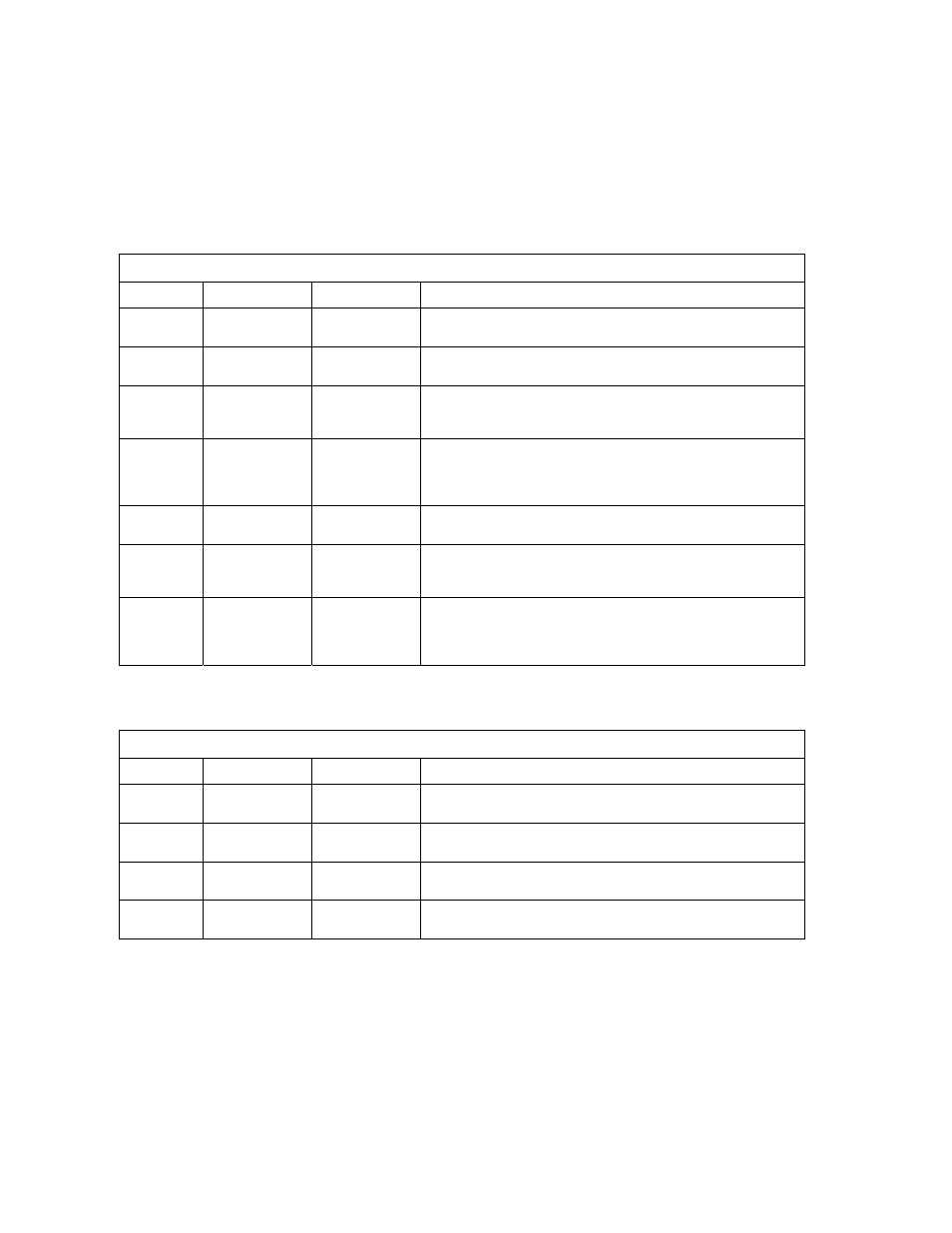
SW 1 (RIGHT SWITCH)
SWITCH FUNCTION SETTING
DESCRIPTION
1 Direction
OFF
ON
Changes open / close direction of operator.
2 Auto
Close
Timer
OFF
ON
Auto-close timer is OFF. Manual input required to close gate.
Auto-close timer is ON. Adjustable from 1-23 seconds.
3 Open
Loop
Output
OFF
ON
Switches logic-level output of EXIT loop port to terminal 4.
Normal Setting
. Control board responds internally to loop
detector plugged into exit loop port.
4 & 5
Relay & LED
4-OFF 5-OFF
4-OFF 5-ON
4-ON 5-OFF
4-ON 5-ON
Relay activated and LED on when gate is FULL OPEN.
Relay activated and LED on when gate is NOT CLOSED.
Relay activated and LED on when gate is OPENING and OPEN.
Relay activated and LED on when gate is OPENING or CLOSING.
6 Warn
Before
Operate
OFF
ON
Normal setting
.
Alarm will sound 2-3 seconds prior to the gate starting.
7 Reverse
Stop
OFF
ON
Normal Setting
. Input to terminal 7 will REVERSE gate during
close cycle.
Input to terminal 7 will STOP gate during close cycle.
8 Quick
Close
OFF
ON
Normal gate operation.
Opening gate will stop and begin to close as soon as all reversing
inputs (loops, beams) are clear regardless of the open position of
the gate.
SW 2 (LEFT SWITCH)
SWITCH FUNCTION SETTING
DESCRIPTION
1 Self
Test
(see note 1)
OFF
ON
Normal setting.
Run self-test – bench test only.
2 Open
Uphill
OFF
ON
Normal setting.
Turn ON if gate opens in an uphill direction.
3 Open
Downhill
OFF
ON
Normal setting
.
Turn ON if gate opens in a downhill direction.
4 Spare
OFF
ON
Normal Setting
.
NOTES:
1. Do not run the self-test while the gate operator is connected to the gate. This self-test
feature is designed for bench-testing only.
Page
34
9210-065-F-11-07