3 chain guide adjustment – Controlled Products Systems Group 9210-081 User Manual
Page 17
1.3
Chain Guide Adjustment
After determining which mounting method is to be used (pad or mounting stand), adjust the chain
guides according to the mounting method being used.
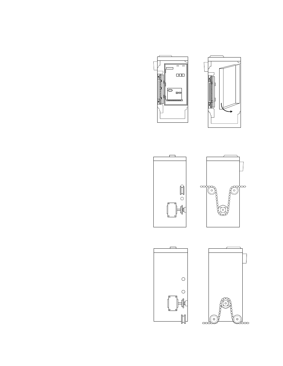
OPEN
To gain access to the inside of the operator,
remove three hex-head nuts from the left side of
the control panel housing.
Pull the housing out and away.
For pad mounted operators, remove the UPPER
hole knockouts from each side of the operator.
Adjust the chain guides as shown.
Chain will be routed OVER the chain guides and
UNDER the drive sprocket.
For operators mounted on the mounting stand,
DO NOT remove any hole knockouts.
Adjust the chain guides as shown.
Chain will be routed UNDER the chain guides
and OVER the drive sprocket.
9210-065-F-11-07
Page
17