1 terminal descriptions, Pin main terminal, Pin non-removable terminal – Controlled Products Systems Group 9000-080 User Manual
Page 33
9000-065-F-9-10
31
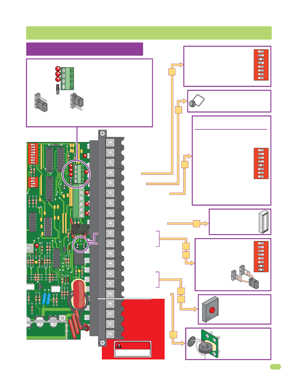
5.1 Terminal Descriptions
Low Voltage Common
Full Open
24 VAC - 250 mamp. max.
Full Open
Partial Open
Standard Reverse or Stop
Gate Tracker Data
Gate Tracker Busy
24 VDC Mag Lock Power
Dry Relay Contact
Dry Relay Contact
Low Voltage Common
Low Voltage Common
Entrapment Alarm
Alarm Reset
Secondary Current Sensor
Motor
Motor
Circuit Board Power
Circuit Board Power
24-volt DC magnetic lock
power is provided constantly
except when the gate is
opening or open (Normally
Closed function). 1 Amp Max.
DANGER
HIGH VOLTAGE!
For long gate applications. An input
device connected to terminal #5 will
open the gate to the partial open setting,
See page 24 for more information.
DoorKing’s Remote alarm reset
station can be connected. See
next page for wiring.
It MUST be mounted in the
line-of-sight of the gate
operator. (DKS P/N 1404-080)
For dual operator applications
ONLY. Allows the secondary
reversing sensor to monitor
the current flow into the
secondary operator. See page
26 for more information.
•
lf SW 1, switch 3 is ON, functions as a
normal full open input (Normal setting).
•
lf SW 1, switch 3 is OFF, input to
terminal #4 becomes the output from the
EXIT loop detector plugged into the EXIT
loop port. (Used for specialized functions).
SW 1
1
ON
2
3
4
5
6
7
8
Operation of relay is dependent on
setting of SW 1, switches 7 and 8.
Relay contacts can be set for
Normally Open (NO) or Normally
Closed (NC) operation.
Contact rating is
1 amp maximum
at 24-volts DC.
NO
NC
SW 1
1
ON
2
3
4
5
6
7
8
SECTION 5 - MAIN TERMINAL WIRING
This input ONLY fuctions when gate is fully
opened or in the closing cycle.
•
When gate is closing: SW 1, switch 5 is OFF,
an input to terminal #6 (eg: photo beam gets
obstructed) will reverse and open the gate.
Note: If the auto-close timer is ON,
when gate reaches the open position,
timer will not close the gate. Another
input command is needed to reset
and close the gate.
•
When gate is closing: SW 1,
switch 5 is ON, an input to terminal
#6 (eg: photo beam gets obstructed)
will stop the gate, then continue to close the
gate when input is clear (Used to help prevent
tailgating vehicles from unauthorized entry).
See page 23 for more information.
SW 1
1
ON
2
3
4
5
6
7
8
Open LED
Close LED
Stop LED
Open N.O.
Close N.O.
Stop N.C.
Common
4-Pin Non-Removable Terminal
20-Pin Main Terminal
1
2
3
4
Jumper on bottom
2 pins when using
4-pin terminal.
Jumper on top 2 pins
when NOT using
4-pin terminal.
Notes:
•
Use a standard 4-wire 3-button
control station.
DoorKing’s 3-wire 3-button
control station cannot be used.
•
When using a 3-button control
station AND a interlock device
together, #3 terminal (N.C.) must
be wired in series.
•
See next page for wiring.
3-Pin with
Jumper
20
19
18
17
16
15
14
13
12
11
10
9
8
7
6
5
4
3
2
1
1
ON
2
3
4
1
ON
SELF
TEST
NC
TIME
DELAY
NO
REV SENSE
PRIMARY
1
2
3
4
5
6
7
8
9
13
12
11
10
14
15
16
17
18
19
20
2
3
4
5
6
7
8
4405-010
9
Relay
Contacts
4
1
2
3
4
5
6
9
10
11
16
15
14