Controlled Products Systems Group 9000-080 User Manual
Page 24
9000-065-F-9-10
22
3.2 DIP-Switch Settings for 4405 Circuit Board
Switch
Function
Setting
Description
SW 1 (Top 8 Switches)
Primary
Operator
Opening
Direction
OFF
ON
OFF
ON
OFF
ON
OFF
ON
7-OFF
7-OFF
7-ON
7-ON
8-OFF
8-ON
8-OFF
8-ON
Auto-Close
Timer
Single Operator
Dual Operators
Relay
1
2
3
4
5
6
7 and 8
The output wired to terminal #4 becomes the output from the exit loop detector
plugged into the EXIT Loop port.
Normal Setting. Terminal #4 is a normal full open input.
Auto-close timer is OFF. Manual input required to close gate.
Normal Setting. Auto-close timer is ON. Adjustable from 1-23 seconds.
Normal Setting. Switch must be OFF for single operator.
Switch must be ON when primary/secondary (dual) gates are used.
Normal Setting. Relay activates when gate is at open limit.
Relay activates when gate is not closed.
Relay activates when gate is opening and open.
Relay activates during opening and closing cycle.
Switch
Function
Setting
Description
SW 2 (Bottom 4 Switches)
Normal Setting. Switch 3 MUST be turned ON for Model 9000 operator.
Normal Setting. Switch 4 MUST be turned OFF for Model 9000 operator.
OFF
ON
OFF
ON
ON
OFF
Magnetic lock
1
2
3
4
Normal Setting. Magnetic lock is not used.
Magnetic lock is used and connected to terminals 9 and 12. See page 32 for wiring.
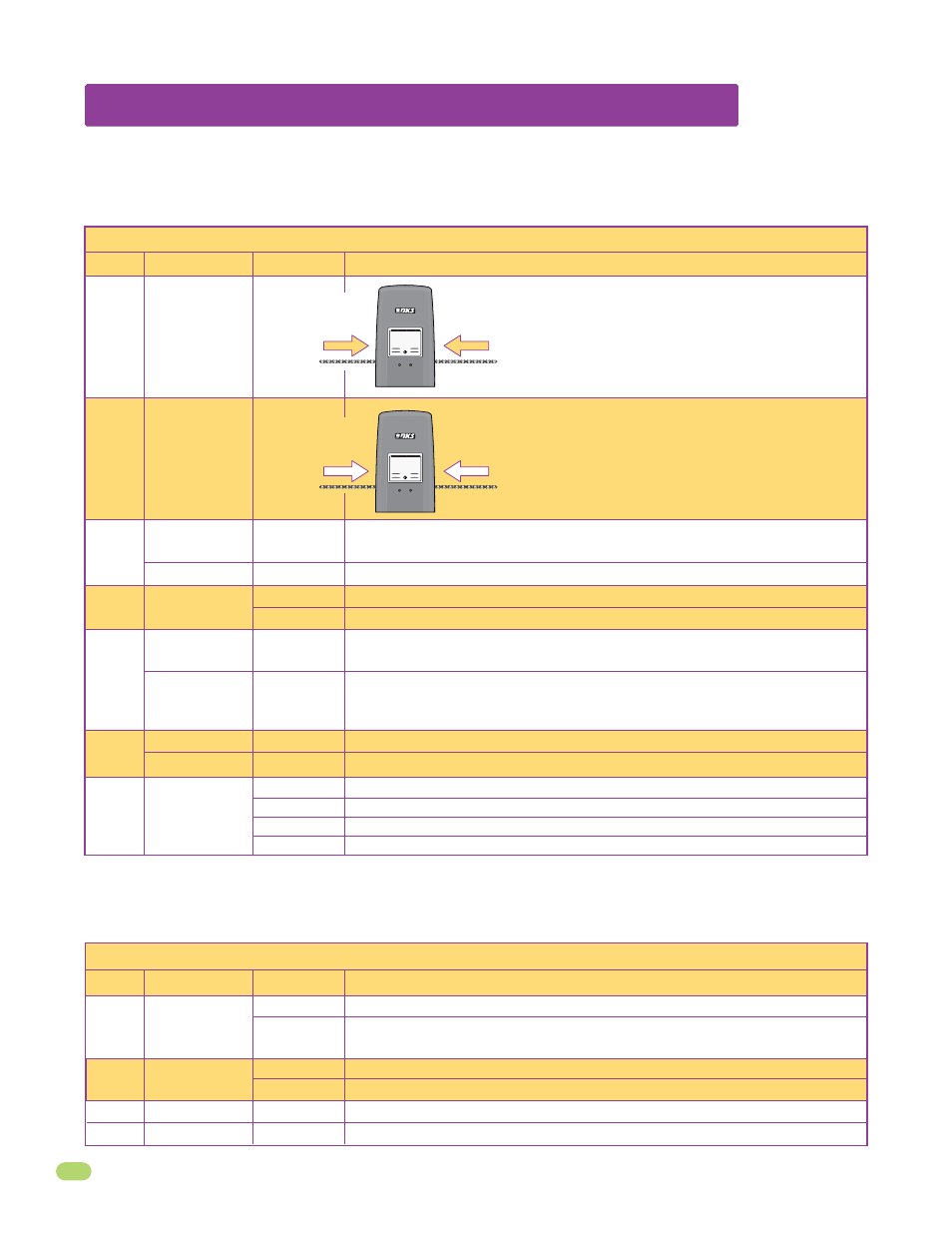
Opening direction
using ON setting.
Opening direction
using OFF setting.
Changes direction operator will cycle open
upon initial AC power up and open command.
Changes direction operator will cycle open
upon initial AC power up and open command.
Opening direction
using ON setting.
Opening direction
using OFF setting.
Secondary
Operator
Opening
Direction
Reverses Gate
Stops Gate
Quick-Close
Timer Override
Exit Loop Port
Output
Full Open Input
Normal Setting. Input to terminal #6 and reverse loop will reverse gate during
close cycle.
Input to terminal #6 and/or reverse loop will stop gate during close cycle – gate will
continue to close after input to terminal #6 and/or reverse loop are cleared (Helps
prevent tailgating).
The two DIP-switches located on the circuit board are used to program the operator to operate in various modes and to turn on
or off various operating features. Whenever a switch setting is changed, power to the operator must be turned OFF and then
turned back on for the new setting to take affect. Check and review ALL switch settings prior to applying power to the operator.
Normal Setting. Timer will function normally.
Opening gate will stop and begin to close as soon as all reversing inputs (Reverse
loops, photo sensors) are cleared regardless of the distance the gate has opened.