Operator installation/ surface operator – Controlled Products Systems Group 1603-080 User Manual
Page 7
1603-065-A-10-06
installation guide 7
operator installation/surface operator
Before installing Operator/Spike system check concrete to be even and leveled, avoiding any Operator/
Spike system unbalance and unevenness.
Conduit requirements may vary depending on your specific needs. Use only sweeps for conduit bends,
do not use 90° connectors this will make wire pulls very difficult and can cause damage to wire insula-
tion. A suggested minimum of 3/4-inch conduit should be used. Be sure that all conduits are installed in
accordance with local codes.
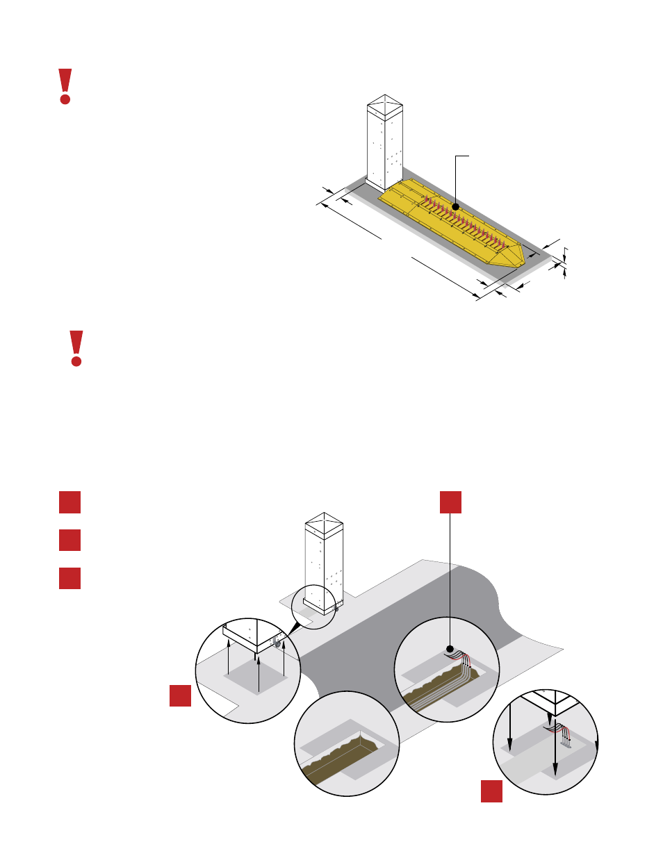
6”
MINIM
UM
D
EPTH
6”
48”
6”
12’ft.
6”
CONCRETE BASE
2
/0%2!4/2
0/3)4)/.
Mix and pour concrete into the trench, al-
low the concrete to cure and place the op-
erator into position.
1
3
From the operator position dig a trench.
NOTE: The trench should enclose the con-
duits.
Run conduits from the operator to their
corrsesponding source .
1
3
•Hi Voltage Conduit
•Low Voltage Conduit
•Loop Lead Conduit
•Sequencing Control or
Primary/Secondary Conduit
2
The operator/spike system must be installed on a concrete
base no less than 6” thick (check your local building codes)
with rebar and/or wire mesh for added strength.
•Concrete base should be even and leveled
avoiding any Operator/Spike system unbalance.
•Mix concrete according to manufacturer.
•Pour and tamp concrete into form.
•Level and surface.
•Allow concrete to cure for 48 hrs.