Electrical installation/ loop detector wiring, 5p $own – Controlled Products Systems Group 1603-080 User Manual
Page 15
1603-065-A-10-06
installation guide 15
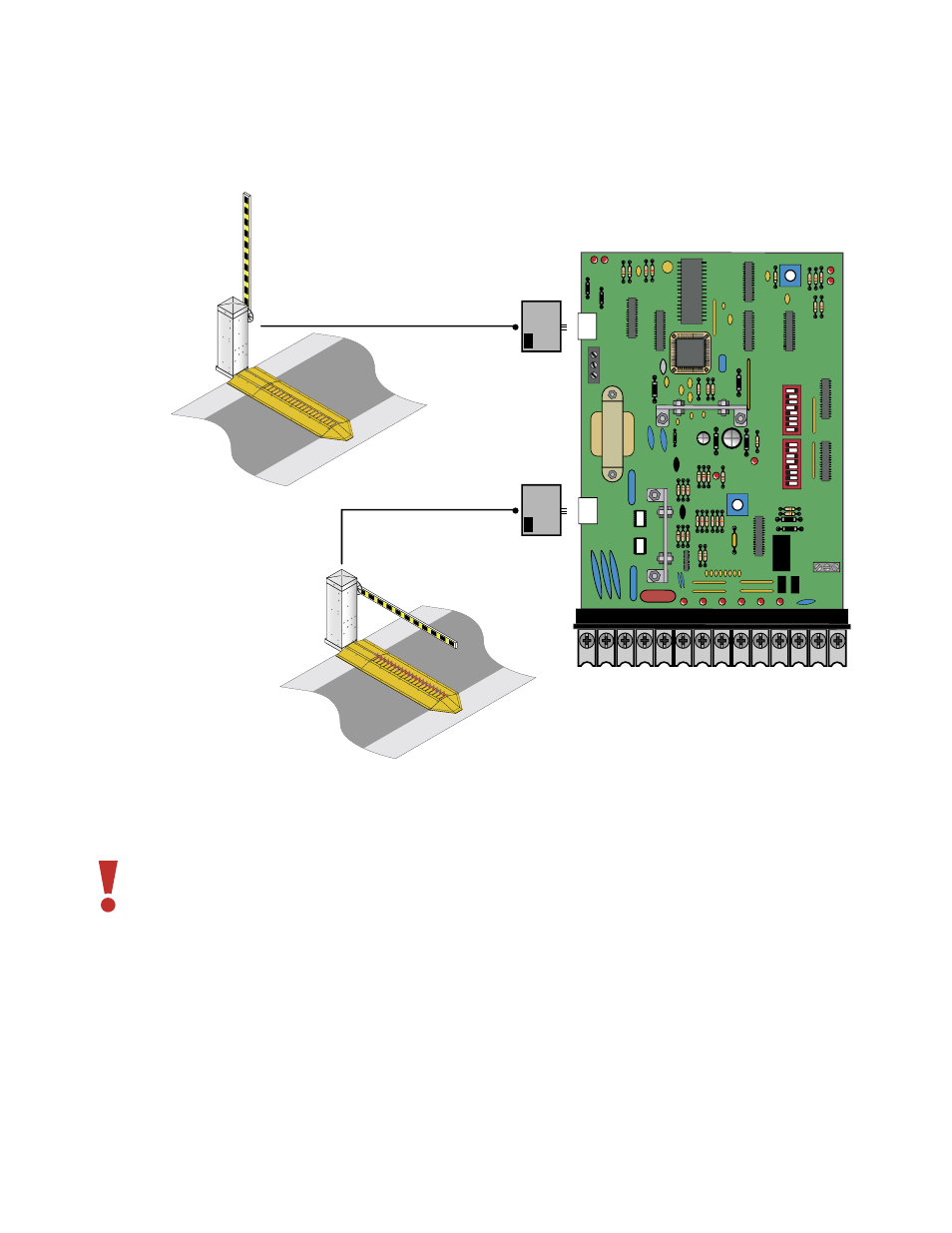
Loop detector wiring shown is for DoorKing model 9409-010 and 9410-010 plug-In loop detectors only.
electrical installation/loop detector wiring
1 2 3 4 5 6 7 8 9
10 11 12 13 14
SW1
S
W2
1
2
3
4
5
6
7
8
1
2
3
4
5
6
7
8
3- DATA OUT
2- DATA IN
1- COMMON
5P
$OWN
TB 1
UP
Detector
TB 1
DOWN
Detector
Power must be turned off prior to making any connections to the terminal strip.
If using other loop detectors, inputs to the terminal strip are NORMALLY OPEN.
If using other loop detectors, refer to the separate.
Loop layouts shown are for typical barrier gate applications.
If using other loop detectors refer to the separate Loop Information Manual for installation instructions,
loops/preformed loops and wiring diagrams.