Controlled Products Systems Group 1603-080 User Manual
Page 22
1603-065-A-10-06
22 installation
guide
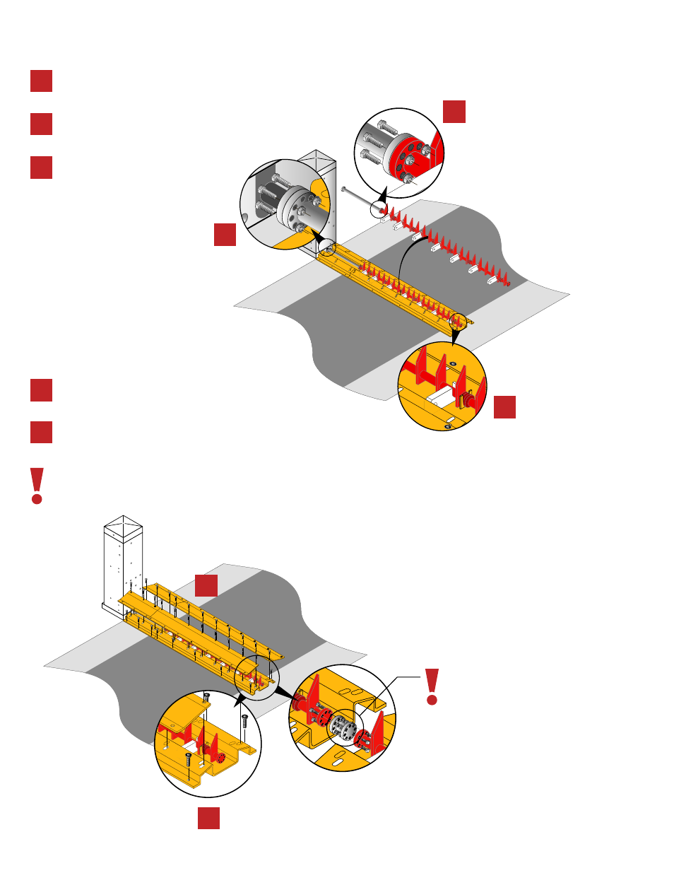
Using 4 bolts (included) attach and
secure the extension shaft to the op-
erator main-shaft.
Set the nylon spike guides and
spike shaft in place.
Using 4 bolts (included) attach and secure
the spike shaft to the extension shaft.
Set the ramp plates into place and
secure them to the spike tunnel us-
ing the provided bolts.
Anchor and secure the spike
tunnels on to the concrete.
For proper spike operation it is recom-
mended not exceed a 12’ ft. spike assy.
A shaft spacer must be installed
between spike units when attach-
ing multiple spike assemblies.
spike installation/surface mount
2a
3a
2b
3b
2a
2c
2b
3a
3b
2c