455 d c – Controlled Products Systems Group 1044682 User Manual
Page 9
Page 9
November, 2003
402 Operator And
455 D Control Panel Installation Manual
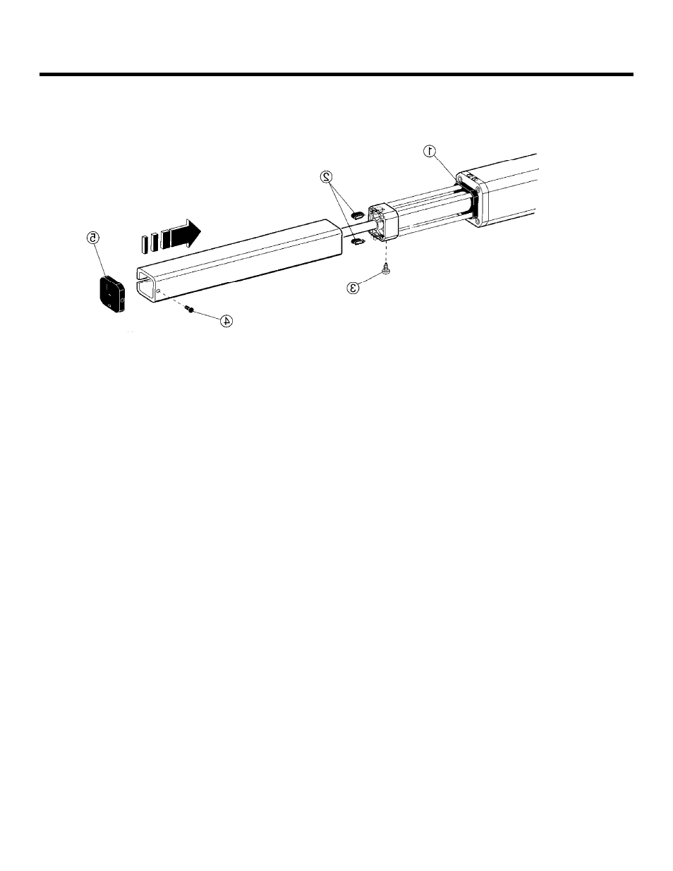
Figure 6. Install the cover for the 402
Operator
I
NSTALLING
THE
455 D C
ONTROL
P
ANEL
Locate the control panel in the most convenient position
possible, considering the movement of the gate. Figure
6 shows a basic layout for a two-leaf gate with the 402
Compact Operator.
Installing the control panel consists of the following
general steps:
•
Connecting the main power to the control
panel
•
Connecting the activating device
•
Connecting the operator to the control panel
•
Checking the direction of the motor's rotation
•
Connecting other devices to the control panel
•
Set operating modes
The installer is responsible for grounding the gate and
operator systems, for providing the main power breaker
switch, and for making sure that the entire gate system
meets all applicable electrical codes.
For the complete 455 D Control Panel Installation
Instructions, see pages 14—25 of this manual.