Npacking, Perator – Controlled Products Systems Group 1044682 User Manual
Page 5
Page 5
November, 2003
402 Operator And
455 D Control Panel Installation Manual
U
NPACKING
THE
O
PERATOR
When you receive your 402 Compact Operator, complete
the following steps.
Inspect the shipping box for physical damage such as
leaking oil or a torn carton. Then inspect the operator
after you remove it from the box. Notify the carrier
immediately if you note any damage because the carrier
must witness the damage before you can file a claim.
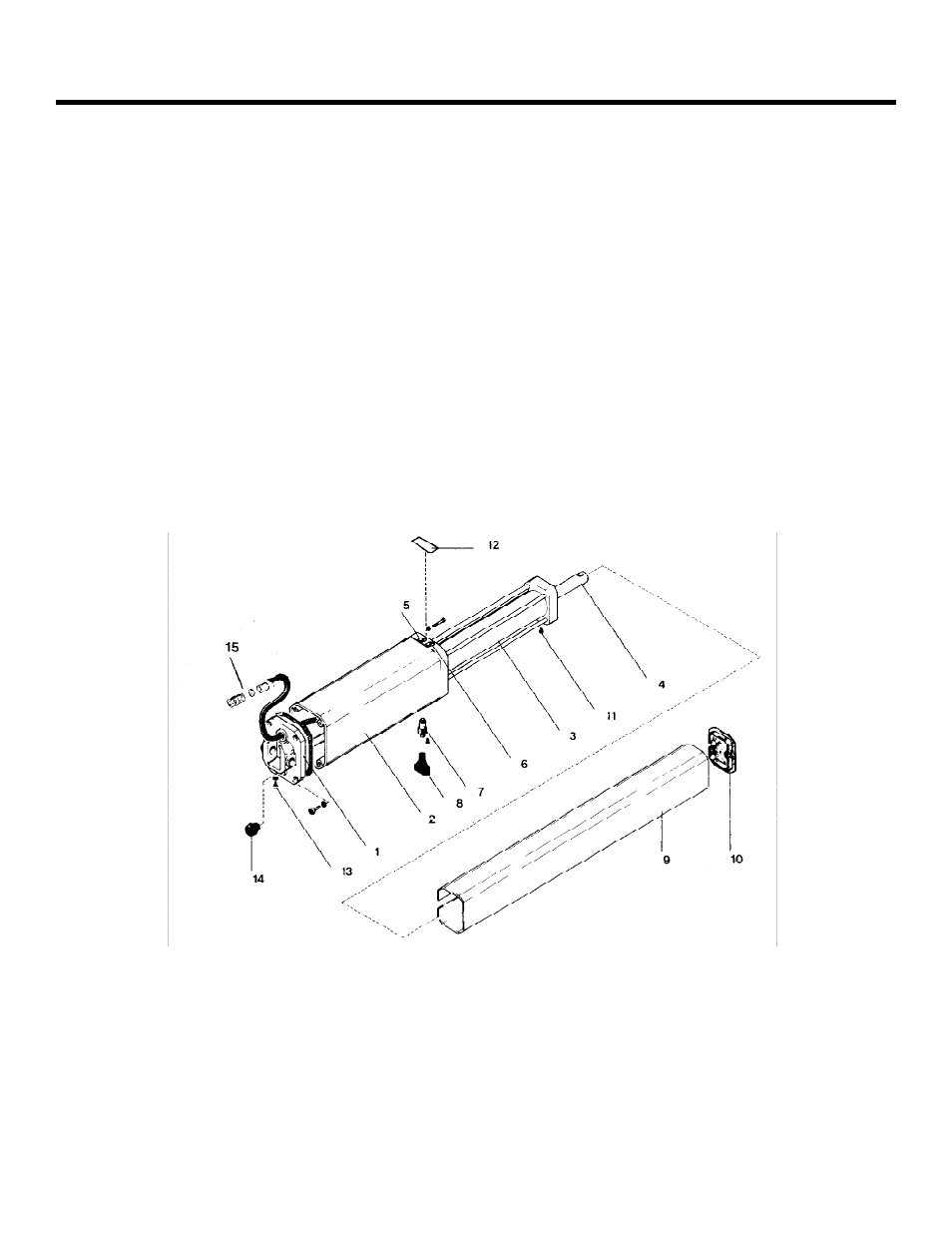
As you unpack the box, insure that all the parts listed
below are included (see Figure 1). If you have ordered a
kit (a pair of operators), you will have twice the quantity
of parts listed below (except where noted), and you will
also have a radio receiver and two transmitters.
1 Control panel box with control panel inside (only 1
per kit)
1 402 Operator unit
1 Protective cover for the operator
1 End cap or guard cover
1 Rear mounting bracket (for post or wall)
1 Rear mounting plate (use is optional)
1 2 in. (50 mm) operator pin with 1 nut for
attachment to rear mounting bracket
1 Mounting fork support
1 2-3/4 in. (70 mm) operator pin with 1 self-locking
nut for attachment to rear flange of operator
1 1-1/8 in. (29 mm) pin for fixing the front coupling
to the operator’s piston rod
2 E clips for either end of the pin fixing the front
coupling to the operator’s piston rod
1 Front
mounting
brackets
1 Nameplate (with 2 screws) for covering pressure
adjustment screws
1 Manual Release key
1
Rear flange
8
Manual Release key
2
Operator casing containing pump and motor
9
Cover
3
Cylinder body
10
Cover end cap
4
Piston rod with hole for attaching to front mounting bracket
11
Cover fixing screw (1 of 2)
5
Green screw for adjusting pressure
12
Nameplate secured with screws
6
Red screw for adjusting pressure
13
Oil vent screw
7
Manual Release Mechanism
14
Oil loading cap
Figure 1. The 402 Compact Operator