Controlled Products Systems Group 1044682 User Manual
Page 8
Page 8
November, 2003
402 Operator And
455 D Control Panel Installation Manual
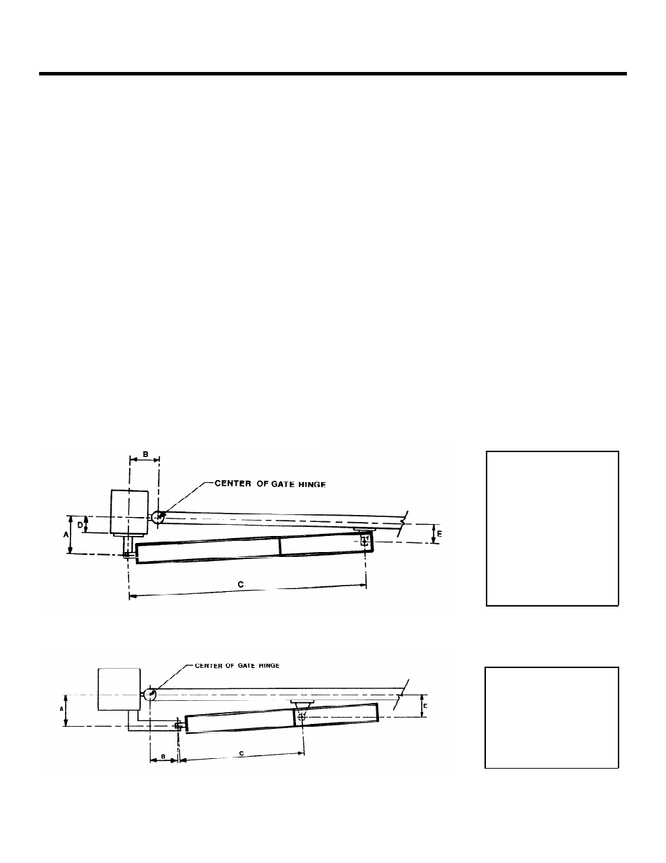
402 Standard
A 4-1/2 in. (114 mm)
B 4-1/2 in. (114 mm)
C 35-1/2 in. (902 mm)
D If greater than 2 in.
(50 mm), construct
a recess liner.
E Must be less than A
Figure 4. An inward swinging gate, top view: important mounting dimensions
Figure 5. An outward swinging gate, top view: important mounting dimensions
402 Standard
A 4-1/2 in. (114 mm)
B 4-1/2 in. (114 mm)
C 26-1/2 in. (673 mm)
E Must be less than A
as instructed below, will ensure proper location
of the front mounting bracket.
Bolt or weld the front mounting bracket to the
marked location on the gate.
WARNING!
Do Not Weld the front mounting
bracket with the operator attached. Doing so
will seriously damage the operator.
A
TTACH
THE
O
PERATOR
TO
THE
G
ATE
Re-attach the operator to the mounting brackets. Once
the operator is mounted and level, remove the vent
screw from the bottom of the valve body. Use a 3mm
hex wrench.
WARNING!
Failure to remove the vent screw may
result in erratic operation of the operator or blown
seals.
Slowly move the gate open and close.
WARNING!
The piston should not bottom out in
either direction. Doing so will seriously damage
the operator.
Be sure that the gate reaches the positive stop
before the piston bottoms out.
After checking the swing of the gate, secure all nuts and
bolts.
Once the operator is secure, install the protective cover
over the piston of the operator, first insert the two
spacers (items labeled 2 in Figure 6) in the front flange
of the operator as shown. The spacers dampen any
vibrations to the operator.
Next, slip the cover over the operator. The slit in the
cover should face the gate, and the cover should be
placed firmly over the rear of the operator cover (item 1
in the figure).
Finally, use the black plastic screws (items 3 and 4) to
fix the cover to the operator and the end cap (item 5).