Controlled Products Systems Group 1042011 User Manual
Page 8
Page 8
February, 20 09
400 O pe rator And
455 D Control Panel I nst allatio n M anual
A
TTACH
THE
M
OUNTING
H
ARDWARE
Insert the rear fork (hex cut up if you have a nylon rear
fork) into the rear flange of the operator. Secure with
long brass pin and self-locking nut.
Screw the jam nut onto the swivel joint. Slide the
washer on next and screw the swivel joint halfway into
the piston rod. Temporarily attach the front mounting
bracket to the swivel joint with the nut and bolt
provided.
A
TTACH
THE
F
RONT
M
OUNTING
B
RACKET
TO
THE
O
PERATOR
Release the operator as shown in Fig. 3. Put the
operator into position and attach the rear fork to the
rear mounting bracket using the short brass pin,
washer, and nut.
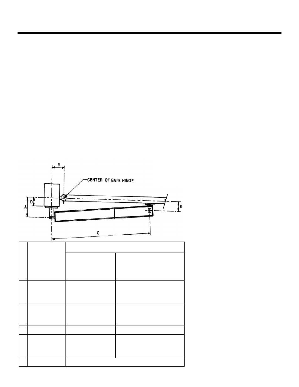
* For A, B, and D, if you choose one
of these values with one asterisk,
then you must choose the other
values with one asterisk.
** For A, B, and D, if you choose
one of these values with two
asterisks, then you must choose the
other values with two asterisks.
For inward swing, pull the piston out completely and
push back approximately ¼” (6mm). For outward swing,
push the piston in completely and pull back out
approximately ¼” (6mm).
Note:
Be sure that the operator is level and that
the gate is against the close positive stop.
Hold the front mounting bracket flush against the gate.
Mark the location of the front mounting bracket.
Remove the operator from the gate. Remove the front
mounting bracket from the swivel joint.
Note:
Clamping the front mounting bracket at the
marked location before checking the swing, as
instructed below, will ensure proper location of the
front mounting bracket.
Bolt or weld the front mounting bracket to the marked
location on the gate.
WARNING!
Do not weld the front mounting
bracket with the operator attached. Doing so will
seriously damage the operator
.
Desired Swing
Dimensions, in. (cm)
400 Standard
High speed and
Slow speed models
400 Long
A
90-deg swing
115-deg swing
125-deg swing
5 (13)
4 (10)
N/A
7 7/8 (20)* or 11 1/2 (29)**
5 3/4 (14.6)
5 1/8 (13)
B
90-deg swing
115-deg swing
125-deg swing
5 (13)
4 3/4 (12)
N/A
7 1/2 (19)* or 3 (7.5)**
7 (17.8)
6 5/8 (17)
C
All Swings
38 3/16 (97)
47 5/8 (121)
D
90-deg swing
115-deg swing
125-deg swing
Max 3 (8)
Max 2 (5)
N/A
Max 5.5 (14)* or 9.5 (24)**
Max 3 1/2 (8.9)
Max 2 3/4 (7)
E
All Swings
Must be less than A
Figure 4. Important mounting
dimensions for inward swing 400
operators, top view