Controlled Products Systems Group 1042011 User Manual
Page 7
Page 7
February, 20 09
400 O pe rator And
455 D Control Panel I nst allatio n M anual
M
ANUAL
R
ELEASE
M
ECHANISM
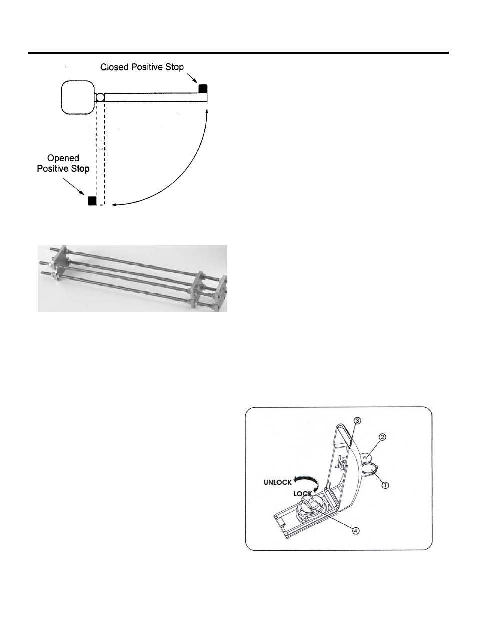
To move the gate operator manually during installation
and/or power failures do the following procedures:
•
Lift the key lock cover (1) and insert the manual
release key.
•
Turn the key (2) 90° clockwise to open the locking
cap cover (3).
•
Lift up the cover.
•
Turn the manual release knob (4) counter-clockwise
for (2) two full turns.
•
Open or close the gate leaf manually.
•
To return the operator to normal working status, do
these steps in reverse order.
I
NSTALLING
THE
O
PERATOR
Installing the 400 operator consists of the following
steps:
1. Attach the rear mounting bracket
2. Attach the mounting hardware
3. Attach the front mounting bracket
4. Attach the operator to the gate
5. Adjust the operator pressure
A
TTACH
THE
R
EAR
M
OUNTING
B
RACKET
Attach the rear mounting bracket according to the
dimensions in Figure 4.
WARNING!
You must achieve the A and B
dimensions, as specified in Figure 4.
Modification of the rear bracket may be
necessary to achieve these dimensions (I.e.,
cutting or extending the bracket provided)
If you have a steel gate post, weld the rear bracket
directly to it. If the gate post is made of any other
material, attach the optional mounting plate, with lag
bolts or anchors, and weld the bracket to it.
For an outward swing gate refer to Figure 5.
Figure 2. Positive Stops
Figure 3. Manual Release