Sensor device – CNB IJB2000 User Manual
Page 8
XNET Network Video Server Installation Manual
8 / 18
z
Power INPUT: Connect 12V DC Power to this terminal.
Please use the power adapter came in the package.
z
STATUS LED : Indicates the operation status
- CPU LED : Green light will blink after 50 seconds on power.
- Video Loss LED : Red light indicates that there is no Video Input signal.
- EVENT LED : Green light indicates that Alarm Out signal is turned on.
- POWER LED : Red light indicates that 12V DC power is connected.
2
2
.
.
3
3
.
.
3
3
.
.
C
C
o
o
n
n
n
n
e
e
c
c
t
t
i
i
n
n
g
g
t
t
o
o
A
A
l
l
a
a
r
r
m
m
d
d
e
e
v
v
i
i
c
c
e
e
s
s
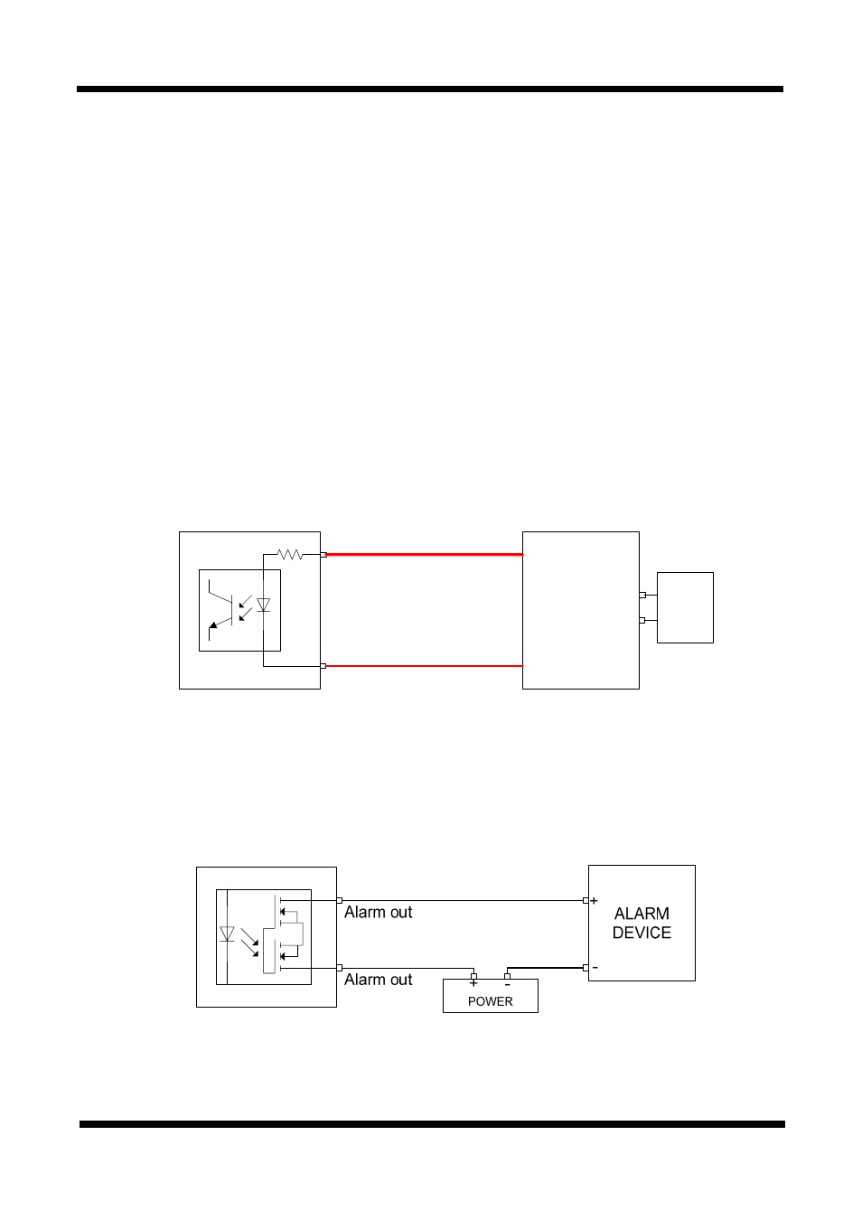
z
Alarm Input
Wires from various sensor type (IR, heat, and magnetic) can be connected to Alarm in(+)/(-) terminal as
shown in figure 2.5. (NC or NO of sensor input can be selected at Menu screen.)
Alarm Sensor device requires a separate power source.
Alarm in(+)
Alarm in(-)
Photo Coupler
Sensor
Device
Signal(+5 ~ 30VDC)
GND
Adaptor
+
-
Internal Circuitry External Circuitry
Figure 2-4. Connecting to Alarm Input
z
Alarm Output
This terminal can only be connected up to DC 30V/400mA. An additional relay device has to be used to
control higher voltage or current.
Internal Circuitry External Circuitry
Figure 2-5. Connecting to Alarm Output