CNB IXP3035VR User Manual
Page 8
XNET Network Weatherproof Camera Installation Manual
8 / 23
2
2
.
.
3
3
.
.
3
3
.
.
C
C
o
o
n
n
n
n
e
e
c
c
t
t
i
i
n
n
g
g
t
t
o
o
C
C
a
a
b
b
l
l
e
e
s
s
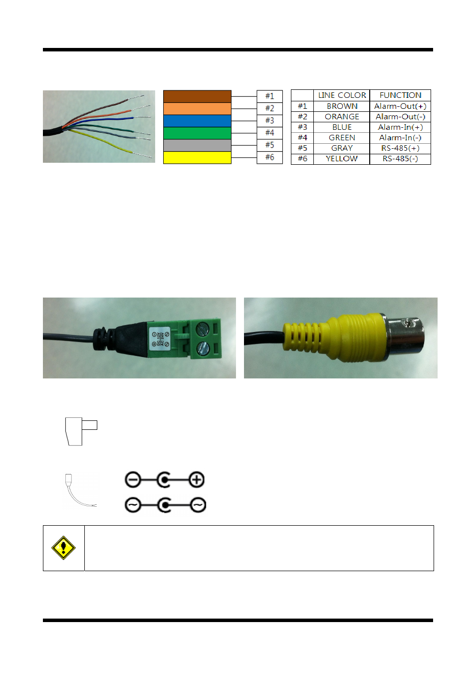
INPUT, OUTPUT
Alarm, RS-485 Connection
These wires connect to Alarm input/output devices.
Alarm Sensor Input: Connect to an Alarm sensor device such as an IR Sensor or a Heat sensor. The
operation of this input can be configured to either
normally close or normally open.
Alarm Output: Connect to a relay that drives alarm devices such as a
Siren Lamp or an Alarm Light.
The operation of this output can be configured to either
normally close or normally open.
Please refer to “2.3.4 Connection to Alarm Devices” for detailed instruction on how to connect a
sensor and a relay.
RS-485: Connect a Pan/Tilt device with RS-485 interface, so it can be controlled over the network.
POWER IN VIDEO OUT
Power Input
Use the cable adapter (DC12V JACK) in the package to connect power.
Please use the power supply provided in the package.
When connecting to a power supply, please note the following power ratings and the
diagrams below: (DC12V/2A, AC24V 2.5A)
Do not use this connector when powering up the product through LAN cable. (PoE)
The product is not covered under warranty when it is damaged by connecting both
Ethernet power and 12V DC power to this terminal.