0 temperature compensation, 0 single transducer operation, 0 troubleshooting – Cleveland Motion Controls Classic Slim Cell Transducer REV AA User Manual
Page 7
INSTRUCTION NUMBER: AO-70165
7of 9
4.0
TEMPERATURE
COMPENSATION
The transducers are supplied with a temperature
compensation network (except size 1 that don’t
require it) which is in series with the output signal
lead. The compensation circuit is designed to be
used with a tension amplifier, which has an input
impedance of 10K Ohms when a pair of transducers
connected as a full bridge is used. If only one
transducer is used, the tension amplifier impedance
should be 5K Ohms. If other than the input
impedances given above are used, drift will occur in
the tension amplifier output when the transducer
temperature changes.
5.0
SINGLE TRANSDUCER
OPERATION
For those applications where only one transducer is
required, a dummy circuit may or may not be
required depending upon the input circuit of the
tension amplifier. Consult the factory for this
information. The dummy circuit consisting of two
resistors is substituted in place of the second
transducer. The resistors should have a resistance
value between 100 and 150 Ohms and should be
matched to within 1%. Dummy circuits are available
from the factory for connecting to tension indicators
or controllers.
6.0
TROUBLESHOOTING
6.1
EXCESSIVE OUTPUT SIGNAL
WITH NO LOAD
There may be a high degree of misalignment of the
transducers causing a severe pre-load.
Or
The sensing guide roll assembly may be excessively
heavy. The sensing guide roll should not weigh more
than _ the maximum working force of the
transducers in most cases.
Or
The transducer may have too small a maximum
working force for the application. Replace with a
higher maximum working force transducer or
decrease the web wrap angle.
6.2
LOW OUTPUT SIGNAL
The transducer may have too large a maximum
working force for the application. Replace with a
lower maximum working force transducer or increase
web wrap angle.
6.3
WRONG POLARITY OF OUTPUT
SIGNAL
Transducers may have been incorrectly oriented. See
Section 2.4 for proper load direction. Alternately,
change the transducer excitation voltage by
interchanging the B and C connections.
6.4
OUTPUT SIGNAL NOT LINEAR, ZERO
SHIFTS DURING OPERATION
Check transducer and tension roll mounting. All
mounting bolts must be tight. Check that there is no
dirt or foreign matter interfering with the transducer
mounting. Check that mounting surface is flat and
rigid.
6.5
NO OUTPUT SIGNAL
Check to see that all connections have been made
completely. Check for places where the connecting
cables might be crimped or cut.
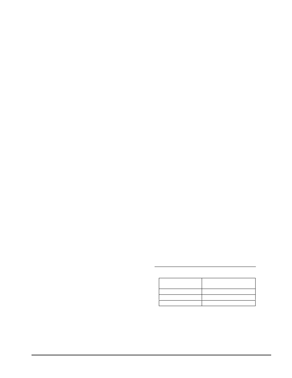
6.6
VERY HIGH OUTPUT WITH NO LOAD
Check cables and connectors for good connections and
check continuity of cables with an ohmmeter. Check
for proper wiring to transducers. Check transducer
gage resistance as given in the following chart at room
temperature with no load applied.
TRANSDUCER GAGE RESISTANCE CHECK
Resistance
(ohms)
SLIM CELL 1 or 2
Pin C to B
420±20
Pin A to B
900-1100
Pin A to C
900-1100