Cleveland Motion Controls Classic Slim Cell Transducer REV AA User Manual
Page 5
INSTRUCTION NUMBER: AO-70165
5of 9
2.4 INSTALLATION OF THE TRANSDUCER
The Slim Cell can be mounted directly to the
machine frame or to the optional mounting bracket.
Mounting the Slim Cell to the Machine Frame
Note that the Slim Cell can be mounted on either
side of the machine frame (see Figure 4). Determine
the arrangement that best suits your application. The
load cell is mounted in place with 3 bolts. Before
drilling and tapping the mounting holes in the
machine frame read the instructions below.
(Orientation and Mounting of the Slim Cell) to
insure that the Slim Cell is properly aligned. The
holes should be located so that load cell can be
mounted to achieve proper alignment. Refer to
dimension B and M in Figure 2 for the proper bolt
hole centers and bolt size. The bolt hole centers are
evenly spaced on a circle and are 120 degrees from
each other.
Mounting the Bracket to the Machine Frame
Determine the correct position for the mounting
bracket. Note that the Slim Cell can be mounted on
either side of the bracket. Refer to Figure 4.
Determine the arrangement that best suits your
application.
Drill and tap two mounting holes in the machine frame
for each bracket. Refer to dimension X in Figure 2 for
the proper bolt diameter. The Slim Cell is mounted to
the bracket with 3 bolts. Before mounting the load cell
in place read the instructions below (Orientation and
Mounting of the Slim Cell) to insure that it is
properly aligned.
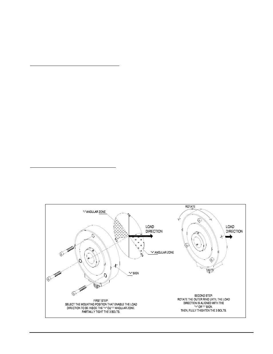
2.5 ORIENTATION AND MOUNTING OF THE
LOAD CELL
Before bolting the load cell in place it must be
positioned so that is aligned with the tension force
(load direction). The Slim Cell is properly oriented
when the load direction arrow (bisector of the wrap
angle- see Figure 7) is pointing along a line
connecting the “+” and “-“ signs on the sides of the
load cell.
Position the Slim Cell so that it can be bolted in place
at the position that is the closest to the proper
orientation. (see Figure 5). Insert the bolts and
partially tighten. To achieve the exact orientation,
rotate the Slim Cell outer ring as required so that the
load direction is pointing through the “+/-“ axis. The
outer ring can be rotated 60 degrees. When the Slim
Cell is properly aligned completely tighten the
mounting bolts. If the force points to the “+”, the